Previous parts
Part 1. How did this all begin?
Part 2. How is 3D data presented in CAD?
Part 3. Precise geometry and tessellation. B-Reps and meshes.

Beginners guide to CAD data
Prepare your business for Industry 4.0, learning how 3D data is presented in CAD.
Get the guide
Beginners guide to CAD data
Prepare your business for Industry 4.0, learning how 3D data is presented in CAD.
Get the guideMaking CAD models look pretty: visual attributes
Visual attributes, like metadata considered in the previous part, can be stored in a CAD model to enrich the data exchange process between various CAD/CAM/CAE applications. Like metadata, visual attributes are not essential to the data exchange process, yet they prove useful if the model is ever displayed (as opposed to just being processed by automatic tools).
Visual attributes can take various forms, such as:
- colors
- materials
- textures
- line styles
- light sources
Let us explore the most important ones.
Attaching a color is the most straightforward way to define the visual appearance of an element on a scene. A colored complex 3D model is not just more visually appealing but is easier to understand (see Fig. 1). Differently colored elements are easier to discern visually for an observer. Additionally, sometimes colors are assigned meaning and they act kind of like layers, described in the previous part. They can identify different physical materials used to produce a part, or some other logical grouping.

In 3D formats, colors are typically specified via RGB (red-green-blue) or RGBA (RGB with alpha, or opacity channel) tuples (see Fig. 2). Some formats (for instance IGES) may use predefined codes to specify the most frequently used colors (plain red, green, white, black, etc.).
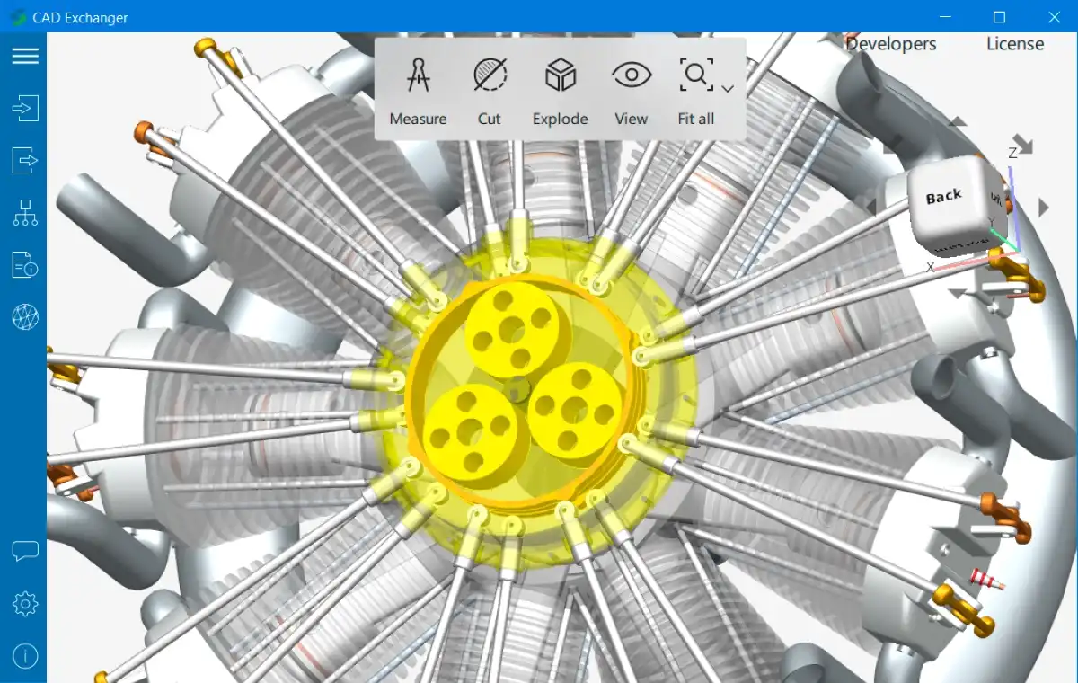
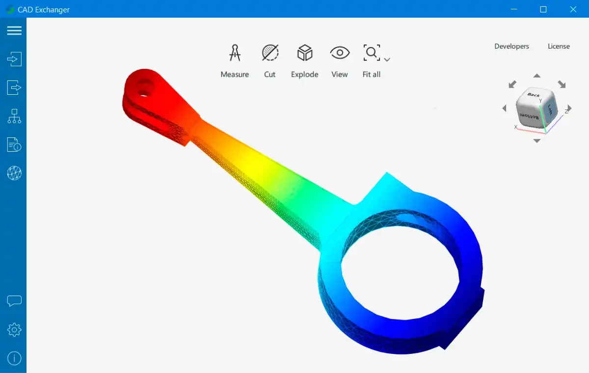
Each CAD format has its own rules for which elements of the model can be colored. Options include (but are not limited to): assemblies, parts and their specific instances in other assemblies, B-Rep bodies, faces or edges (see Fig. 3 and 4). Meshes can be painted completely with a single color, or using so-called vertex colors - when each vertex of the mesh has its own color and in each triangle, the colors of its vertices blend smoothly in the triangle's interior (see Fig. 5).
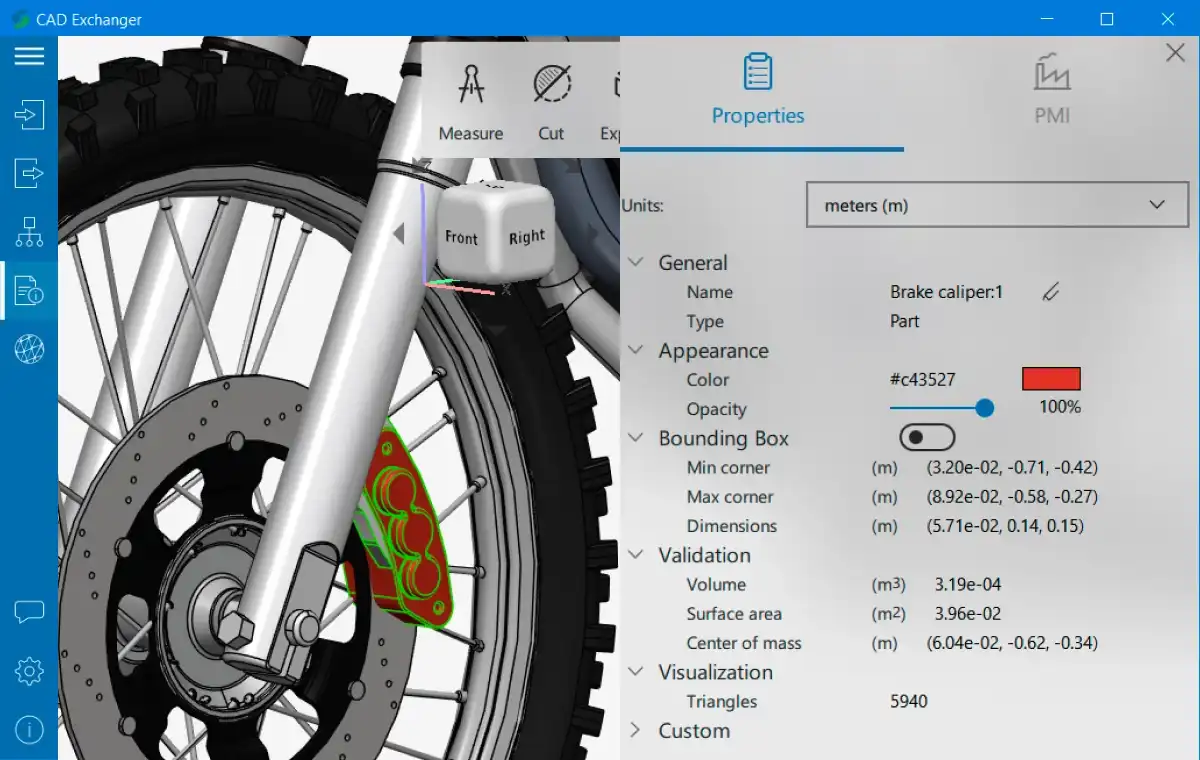
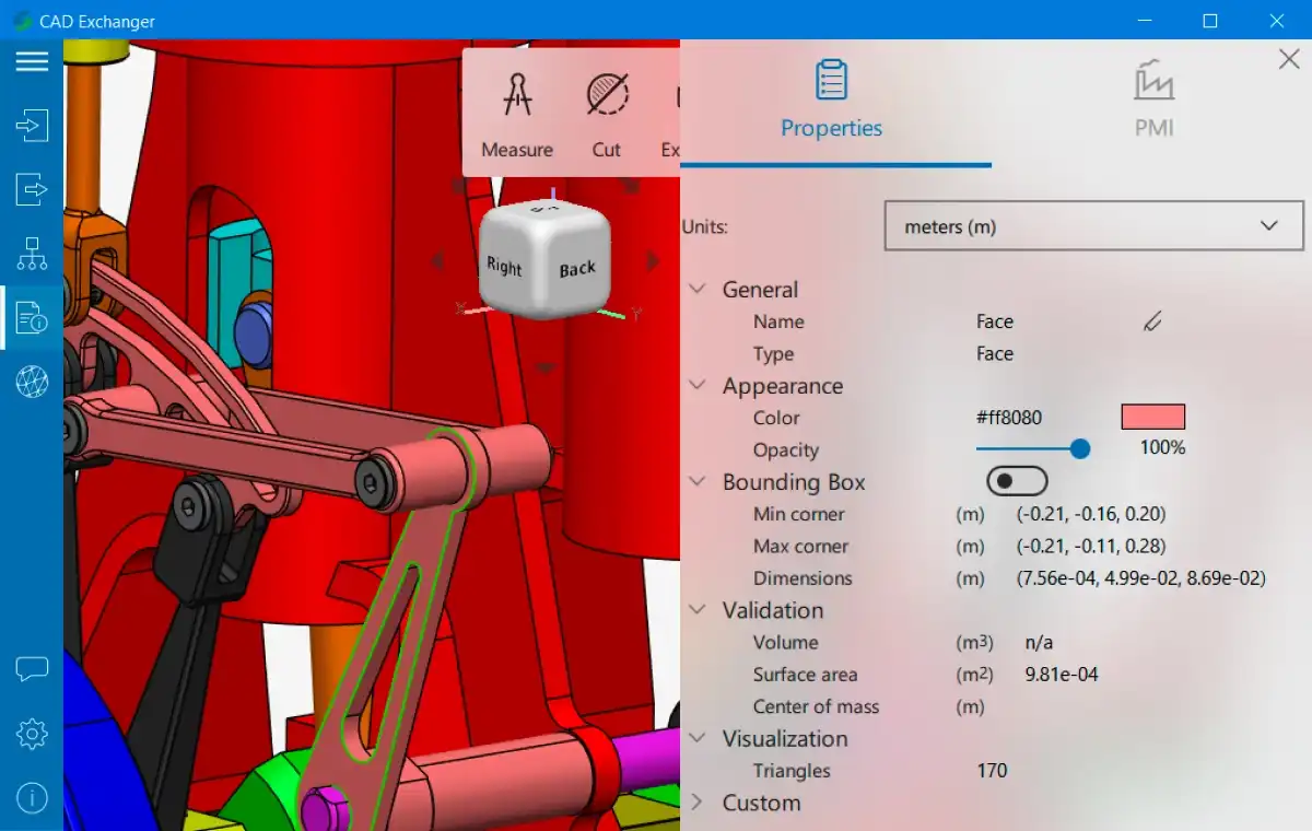
Such an abundance of options creates an ambiguity: how should the model look if the designer colors an element differently at different levels (e.g. at levels of assembly and part, or at levels of part and B-Rep face)? The formats generally follow one or both of the following approaches: restrict the sets of elements that can be colored (until a few years ago, Parasolid-XT only allowed to color B-Rep faces and edges), or specify how the colors at different levels should be inherited/overridden.
Materials extend the idea of single color assignment by encapsulating a group of several colors: diffuse, ambient, emissive and specular, as well as additional parameters, such as shininess. CAD format specifications often follow the OpenGL convention and define floating-point RGBA values in [0, 1] range. Using combinations of RGBA tuples for each color component it's essentially possible to imitate real-world materials, for instance:
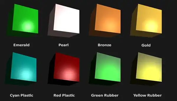
(licensed under CC BY 4.0, original work)
For an even richer visual appearance, some 3D formats enable storage of textures (see Fig. 6). Textures are usually images (i.e. PNG, JPEG, TGA files), which in the simplest form contain color information for various points in the mesh. The correspondence between 2D image and 3D mesh is established with so-called UV coordinates stored in the mesh. They can be thought of as coordinates of mesh vertices in the image, when the mesh is unwrapped onto the texture. Just like with materials, it's often possible to layer multiple textures to specify different aspects of an object's appearance: diffuse, specular and emissive textures imitate an object's material composition, while bump, normal and displacement maps emulate geometric features on the object's surface which don't warrant representation in actual mesh.

At last, some 3D formats (e.g. IGES, VRML, X3D, JT) allow one to transmit various other styles. Examples include line styles (solid, dashed, dotted and so on), line thicknesses, point markers and so forth. These styles are typically only relevant for 2D data-focused formats, such as DXF or DWG, or 2D drawings in 3D-oriented formats, such as IGES. Therefore, 3D-focused applications routinely ignore these capabilities both when reading and displaying models and when writing them.
Related reading:
CAD Exchanger SDK – colors, materials, textures
CAD Exchanger SDK – supported formats