What is Drawing mode?
In the release 3.21.0, we added the Drawing mode in CAD Exchanger Lab. It is a tool specifically designed for viewing and analyzing drawings in the popular DWG file format. With this mode, you can easily open files, explore their contents, and then export files in DXF format.
Who is this tool for?
The Drawing mode in CAD Exchanger Lab is a versatile tool that caters to a wide range of professionals. It is a great find for architects, engineers, and designers who work extensively with DWG files, as it provides them with a user-friendly way to analyze and collaborate on intricate drawings.
- Architects and engineers can take advantage of this feature to easily view DWG drawings, making it simpler to communicate design intent.
- Interior designers can use this tool to explore intricate details and dimensions, ensuring accurate placement of furniture and other objects.
- Contractors and manufacturers can utilize the Drawing mode to review construction plans and ensure precise implementation.
Drawing mode activates automatically when a DWG file is being imported.
Key features of Drawing mode
Dark mode
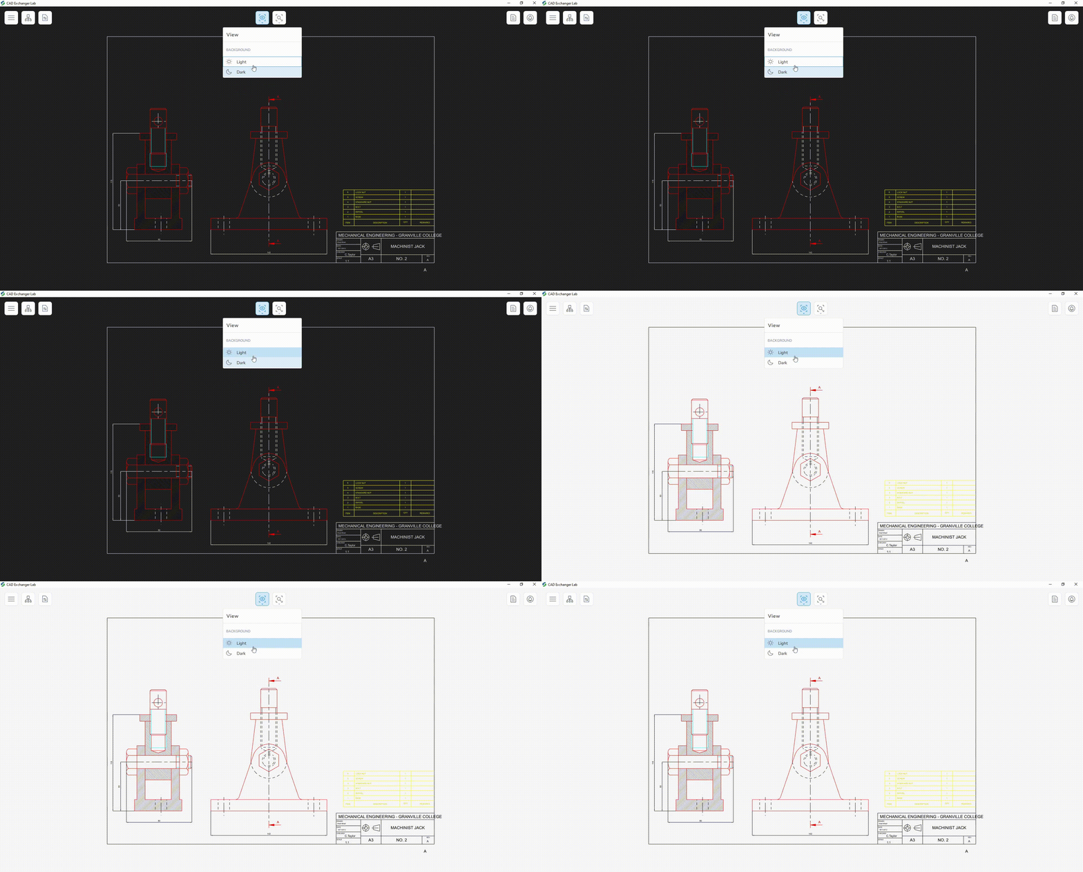
The dark mode feature in the new Drawing mode of CAD Exchanger Lab offers a visually appealing and comfortable viewing experience. With dark mode, the background and color of elements adopt a darker color scheme, which can be easier on the eyes, especially in low-light environments or for prolonged usage.
By enabling dark mode, you can enhance the contrast between the drawing and the surrounding interface, allowing you to focus more on the details of the drawing itself. This feature also helps reduce eye strain and fatigue, making it particularly useful for professionals or individuals who spend extended periods working with DWG drawings.
Specific structure
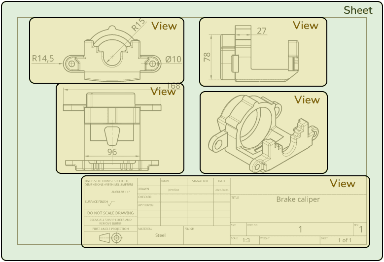
The structure of drawings is relatively simple and can be divided into two main types: sheets and views.
Sheets are like virtual canvases where you can place your views. They represent individual drawing pages and can be used to contain different views of your design. Typically, a drawing has multiple sheets, each containing a few different views. Think of sheets as separate pages in a drawing set, each representing a specific aspect of your design.
Drawing views, on the other hand, are depictions of the model from some side or angle. They are an essential aspect of any CAD software. Drawing views can be isometric or any other projection that helps you showcase specific details or perspectives of your design.
The example below is composed of a single sheet with four drawing views (3 side views and 1 isometric view).
Drawing elements
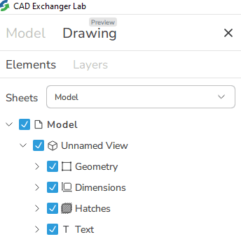
Layers in CAD Exchanger drawings serve as groups for organizing drawing elements. Each element can only belong to one layer. Layers help to categorize objects based on their function or purpose and provide control over properties.
The actual contents of drawings are 2D geometry in the form of curves, piecewise contours, and points. Aside from it can contain dimensions, hatches, and text blocks. There are multiple types of dimensions available, such as length, angle, radius, and diameter measurements.
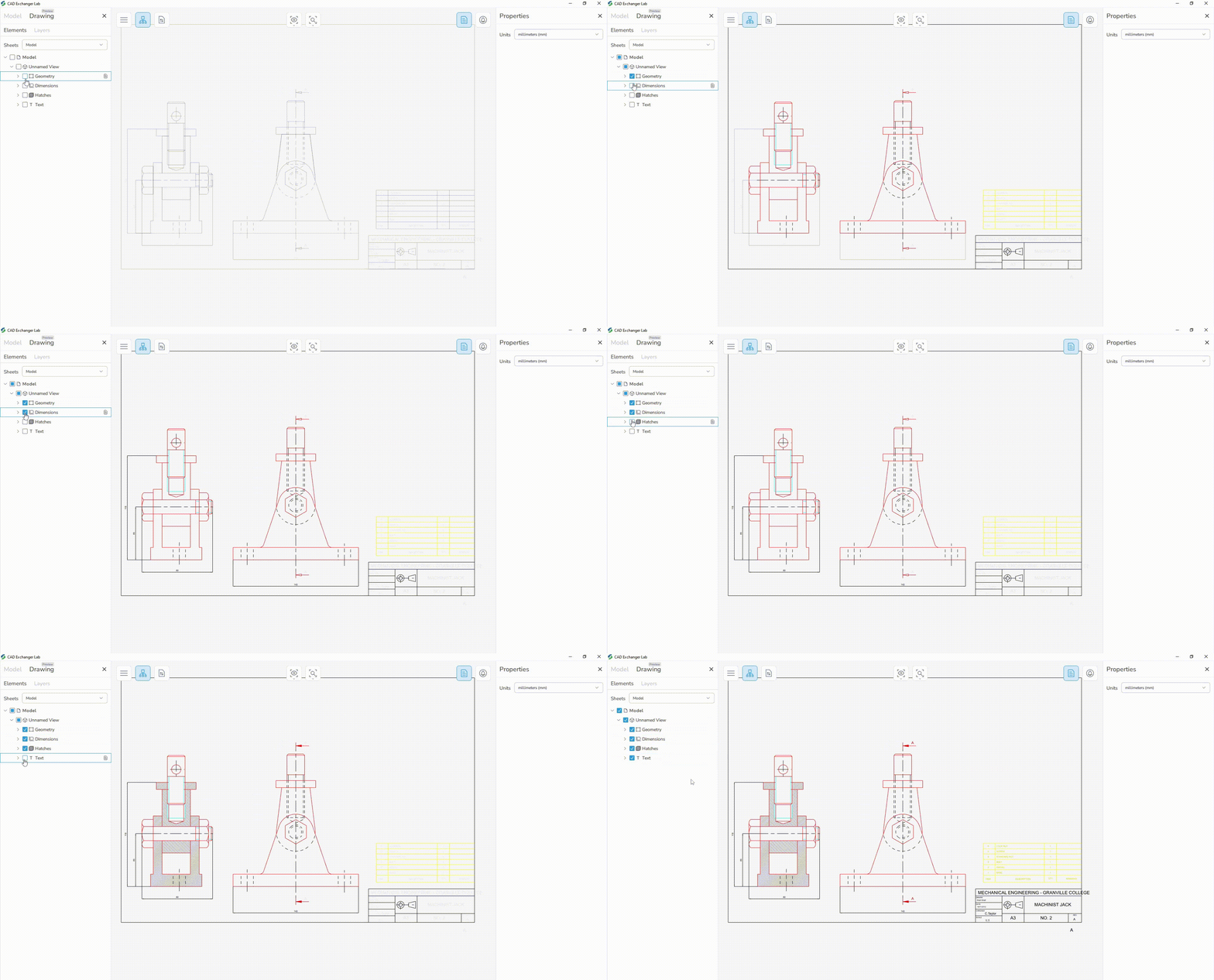
Drawings often also include various other types of data, such as notes and tables. These elements provide important contextual information and help enhance the overall clarity and understanding of the drawing. At the moment, CAD Exchanger drawings cannot represent these features, but there is a possibility of adding them in the future.
Support of 2D and 3D representation
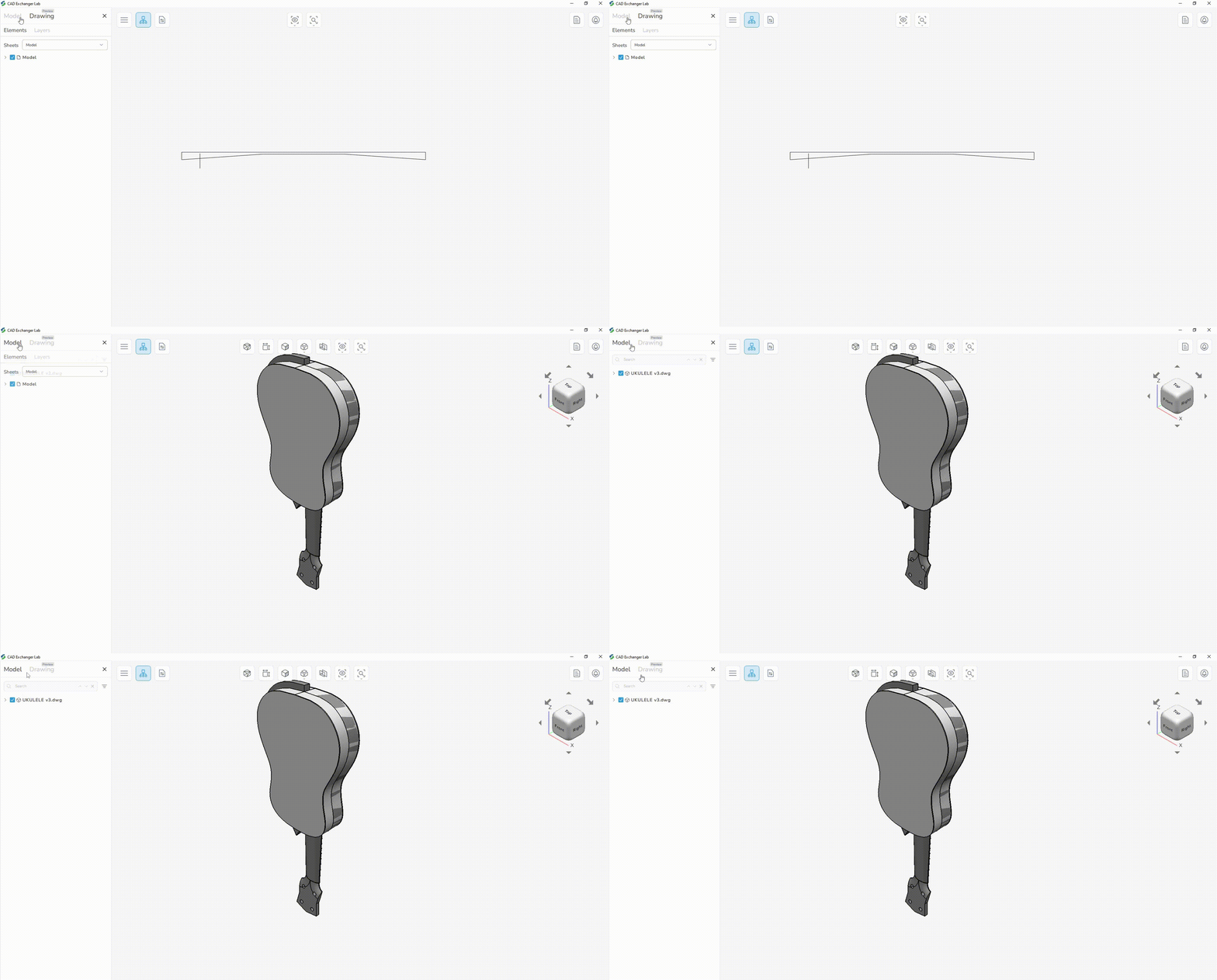
The drawing mode provides you with the flexibility to switch between 2D and 3D data if the model in DWG format contains all the above mentioned data. The user can also load a 2D model, and then load a 3D model with the 'Add to current' checkbox enabled.
Properties
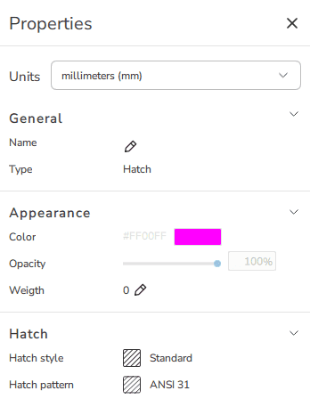
As for the properties, there are two main options: custom and read-only. The general information includes name and type. The appearance section of the particular element may consist of color, opacity, weight, and line type. Hatches have their style and pattern. You can set a name, but other properties are currently read-only. In future releases, users will also be able to change the color, weight, and line type.
For the model itself, the appearance section of drawings includes options for paper size, ranging from A0 to E, and orientation. The available sizes in CAD Exchanger Lab range from A0, which is the largest, to E, which is the smallest. Orientation, in turn, determines the alignment of the drawing on the chosen paper size. It can be either portrait or landscape mode, depending on the content and design of the drawing.

Summary
The Drawing mode allows users to access and view important design information stored in DWG files, including geometry, hatches, dimensions, and text blocks. The structure of drawings consists of sheets, which act as containers for organizing and drawing views, allowing users to analyze comprehensive representations of their designs in a structured and organized manner. With enhanced visualization tools, users can zoom, pan, and inspect the design in detail, facilitating a better understanding of the intricacies of the design.
Overall, the drawing mode in CAD Exchanger provides compatibility, accessibility, collaboration, and enhanced visualization for working with DWG files seamlessly and efficiently.