Ever increasing complexity of the products leads to complex multicomponent assemblies with sophisticated hierarchies. Therefore, sometimes it’s challenging to visually explore 3D files and understand the underneath of the designs.
To simplify this task, we introduced ‘ghost’ mode that would add transparency to certain elements and sectioning tool, which ‘slices’ the design. With the previous release of CAD Exchanger we added third approach to solve this issue. Since CAD Excahnger 3.4.1 users can ‘explode’ the model. Isn’t it exciting?
This blog post will be dedicated to technical and mathematical details of implementation of exploded views in CAD Excahnger. Actually, there is excellent paper about algorithm for exploded view published by Berkley University. http://vis.berkeley.edu/papers/exview3D/exview3D-SIG08.pdf. The used approach is inspired by this article and contains solutions for unsolved problems and implementation difficulties. Let’s begin by leveraging simple algorithm, which would give us acceptable results.
For simplicity, we will base our thoughts around bounding boxes.
To begin with, we have to find the ‘epicenter’ of the explosion. There are few options:
- Point of origin
- Center of the largest bounding box
- Center of the main bounding box
The first option is not viable due to the fact that sometimes model can be displaced from the origin, so explosion could go poorly. Second option could do a trick, but what if there are two or more identical bounding boxes? The third option looks most suitable, so let’s proceed with it.
Take a look at the following 3D model.
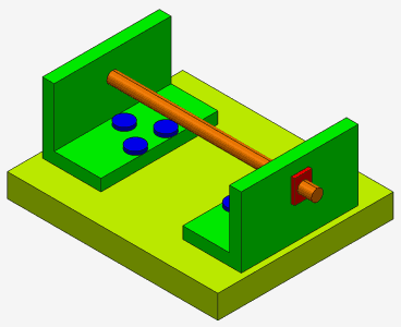
On the image below there is a bounding boxes and their centers, marked blue. The center of the main bounding box is marked red. The lines connect the red dot with the blue ones and represent the trajectories along which we want to move the objects.
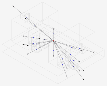
The trajectories match with the directions vectors from the center of the main bounding box to the centers of the secondary bounding boxes. Formula is pretty simple:
a = t * (x1 - x2, y1 - y2, z1 - z2)
where
t – displacement factor,
p (x1, y1, z1) - centre point of n-th bounding box,
q (x2, y2, z2) - centre point of main bounding box.
Where t is an offset coefficient. For example for t=2 we will get the following image:
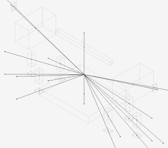
Pretty effortless and viable solution. Let’s test it on more complex model:
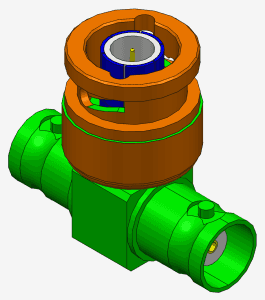
If we apply coefficient t=2,5 (first image) or t=5.0 (third image), then we can see that there are some parts that move jointly.
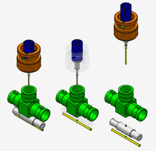
It happens because their centers match. Let’s add some heuristics to solve that issue.
- If we move the object with the nonzero coefficient (t=5) and for n bounding box there is a bounding box that intersect or contain the original bounding box, then let’s save these objects to a container
- After that let’s traverse the container and compute τ for each object. This is needed to increase the offset coefficient: t*=t+ τ. Computation algorithm can be different. I’d recommend to compare the bounding boxes of the objects placed to the container, the smaller the bounding box, the more delta T is applied.
As a result we’ll have the following picture:
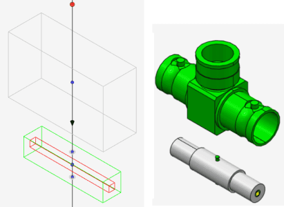
This algorithm is simple, yet powerful. It’s not bullet proof and you may experience the issues on very complex models, but for majority of the cases it will be just fine.