Variety of 3D data types often can lead to confusion, especially for novice users. File formats, suitable for certain tasks, cannot be used in other cases. For example, vast majority of CNC machines do not support mesh data (like STL, OBJ or VRML). To operate them you need B-Rep input (STEP, IGES or other). This is inconvenient, as typically the source 3D file is available in polygonal file format only. This is extremely common in the dental field. Dentists use intraoral scanner to produce mesh 3D model for further usage in CAM software, which does not process mesh files. To enable this workflow conversion is needed.
And here is why we feel important to give a detailed explanation of the root-case. The issue is a conversion from a mesh-based format (such as STL) to a format based on precise geometry, what is not meaningful or efficient.
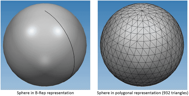
As a rule 3D models are described using two distinct approaches – accurate and approximated. The former uses precise geometrical representation (so called B-Rep, or Boundary Representation) and the other uses polygonal representation (also often referred to as faceted, tessellated, triangulated and so on). The following two images demonstrate the difference on the example of the simplest solid sphere:

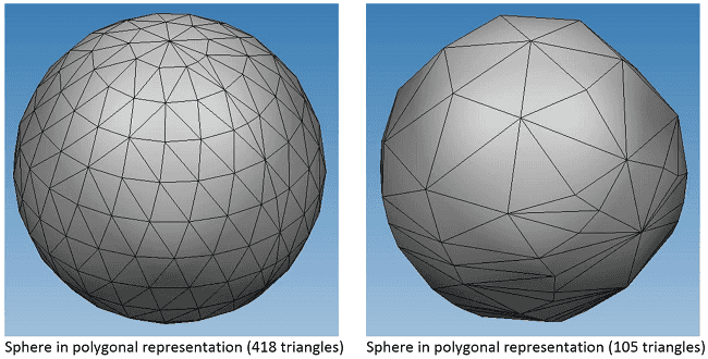
The B-Rep representation of a sphere uses sphere’s placement (center and local axes orientation) and radius. This is a compact precise definition from which a sphere can be accurately constructed and used (e.g. for evaluation of points, normals, etc). The polygonal representation consists of triangles connecting nodes. In the case of a sphere, nodes would lie on a spherical surface. The number of triangles in the polygonal representation depends on accuracy used when approximating the original precise B-Rep representation. This process is called meshing, tessellation, triangulation or alike. The images below demonstrate the same original B-Rep sphere tessellated with different precisions:
IGES, STEP, ACIS, Parasolid and other similar formats use B-Rep representation, whereas STL, VRML, X3D and others use polygonal representation. JT format may contain both.
Thus, converting a model from any B-Rep based format (such as IGES or STEP) to a mesh-based format (such as VRML) is relatively straightforward. However the opposite (for instance, from STL to IGES) is practically impossible – recognition of free-form geometrical surfaces (which can be thousands) from an arbitrary set of triangles is non-deterministic, hardly feasible, unreliable, and would require a lot of compute time.
That is why CAD Exchanger warns a user about the issue until he/she clearly understands the problem and enforces the application to proceed. In the latter case, CAD Exchanger will simply create B-Rep planar surfaces for each original triangle. This will result in huge growth in model file size and the output model (e.g. in the IGES format) will not be of practical use in any CAD system except for visualization. However, for visualization purposes any other mesh format would work even more efficiently.
As JT file can contain both B-Rep and polygonal representation, the warning is only issued when an original JT file only contained a polygonal representation without B-Rep. In the case of JT with B-Rep, the application just proceeds successfully and no warning is issued.
Recommendations
For relevant workflow (when the target format is B-Rep based) the original model should come from a B-Rep based format – an example of such is STEP to JT conversion. If this is impossible and you clearly understand the issue and its implications then just enforce the CAD Exchanger Lab application to proceed and export to a target format of your choice.