Modern CAD software differs greatly in their range of tasks and graphical interface, but it all have one thing in common – typical viewing modes. In fact, this is a limited set of views, surface display modes and detailing. When we are working with 3D-models, a number of view modes are used especially often. We will talk about it in this series of blog posts
Moving from the general to the specific, we consider the most popular viewing modes in 3D CAD software:
Part 1. Isometric view
Part 2. Perspective view
Part 3. Shading
Part 4. Wireframe
Part 5. Section view
Part 6. Exploded view
Each view mode has its own purposes. So, isometric and perspective projections determine the perception of model’s dimensions and proportions, shading and wireframe modes determine the perception of surfaces, and section and explosion allow you to get detailed (initially hidden) information about the 3D-model. At the same time, all view modes have a common goal – to make the user's work more convenient and efficient.
What is isometric drawing?
Isometric projection is one of the types of axonometric projections, which is an image of geometric objects in a drawing using parallel lines. The opposite of an axonometric projection is a perspective projection, in which objects are depicted by lines passing along invisible non-parallel rays, connecting at a projection center remote from the observer.
Axonometric projection includes three types:
- isometric projection, which has the same distortion along all three axes (we consider it in the article);
- dimetric projection, which has the same distortion along two axes;
- trimetric projection, which has different distortions along all three axes.
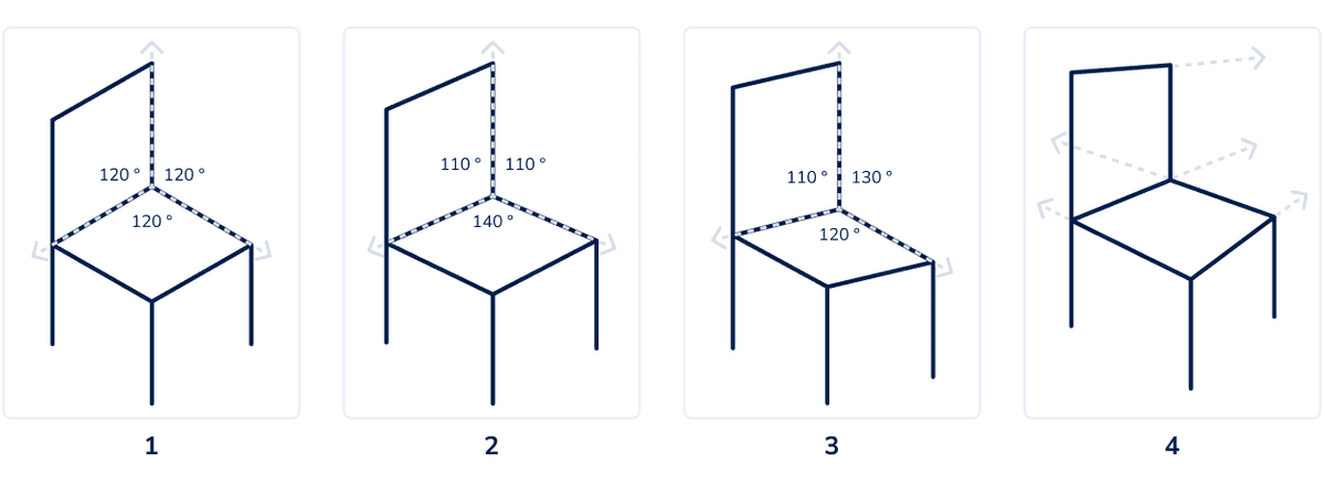
Fig. 1 clearly demonstrates the differences between these projections.

An isometric projection is a type of axonometric projection in which a 3D-model is displayed on a plane with the same distortion factor in all three axes. The X, Y and Z scales are equal and the angle between the axes is always 120°, while in other types of axonometric projections, as well as in non-axonometric projections (for example, in perspective) this is not the case.

(Image source: pixabay.com)
Advantages of isometric view
Isometric perspective is supported by most modern 3D CAD software, including being used as the default view mode. What features make it preferred?
1. Simplicity
When you need to quickly show that an object is three-dimensional without delving into the nuances of its shape, isometric view is the obvious solution. You can quickly and accurately draw an object in isometric perspective with any CAD-program to visually convey its three-dimensionality. You need no complicated calculations for this.
Also, due to its simplicity, isometric view “rules the ball” in the gaming industry. Many game worlds are initially isometric in nature, so the 3D design of their objects is developed in isometric perspective.
On the other hand, if the three-dimensionality of an object needs to be conveyed as realistically as possible, the simplification of the isometric view, on the contrary, will become a disadvantage, and it will be more logical to use a perspective projection.

(Image source: pixabay.com)
2. Response speed
Visualization of 3D-models, its panning, shifting, rotation, zooming in and out, especially when it comes to complex assemblies with a degree of subassemblies and parts, requires a significant computing resource. The amount of calculations depends on the applied view.
Objects in isometric projection can be freely rotated and moved without redrawing. This significantly reduces the processor load, which ensures smooth movement and instant response of the 3D-model to user actions.
When using other views, in particular, perspective, it is impossible to reuse the traced elements – with each movement, its proportions will change, which will require new calculations.
3. Visibility of measurements
When using perspective view, metadata removed from us on the stage, starting with linear dimensions, may look too small. To consider them, you will need to use additional operations – for example, approximation or rotation. Also, to capture these dimensions through printing or rendering, you will need to print multiple views and flatten multiple renders.
In the case of simple models, these steps are redundant and time-consuming, especially when there are many models. If you use isometric view instead of perspective view, the metadata will become equally visible in different parts of the scene, and the need for unnecessary actions will disappear.
4. Unambiguity
Isometric drawing is the best solution when you need to emphasize parallelism or the same size of planes and lines. For example, about a cube depicted in an isometric view, it can be unambiguously stated that it is a cube.
However, as soon as it is placed in a perspective projection, the uniqueness will disappear: the sides of the cube will be distorted by the perspective, and the question of their parallelism will arise. Non-parallel sides can also differ in length. Therefore, we may not have a cube in front of us, but a quadrangular prism.
Disadvantages of isometric view
If isometric perspective were ideal for all cases, it is likely that support for other projections in CAD software would not be needed. But it is not so simple. Isometric projection cannot be called universal for a number of reasons.
1. Unrealistic
In tasks where realism comes first, the isometric view clearly loses to the perspective view.
2. Distortions in the object’s location
In fact, this is a consequence of the previous point. Without applying perspective, it may seem that visually objects are not located where they really should be. This is similar to the effect of car mirrors (“Objects in the mirror are closer than they appear”), but much more complex.
Distortions in the location of objects can be misleading, lead to errors in the construction of 3D-models, slow down work in CAD software, and possibly even lead to incorrect engineering decisions.
3. Restrictions in displaying curves
Isometrics are great for conveying parallelism, but can be useless when trying to convey properties of curves.
4. Impermanence of 3D
Although an isometric drawing is intended to reflect the three-dimensionality of objects, this becomes impossible if you look at the object parallel to one of its axes (that is, when X=0, Y=0 or Z=0).
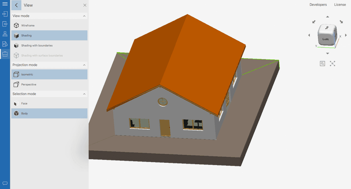
So, Fig. 4 shows a section of the facade in isometric view. With a strictly frontal view (X=0), we get a flat 2D-image, which does not allow us to judge the length of the building and the relative position of its internal elements (furniture, doors, etc.).
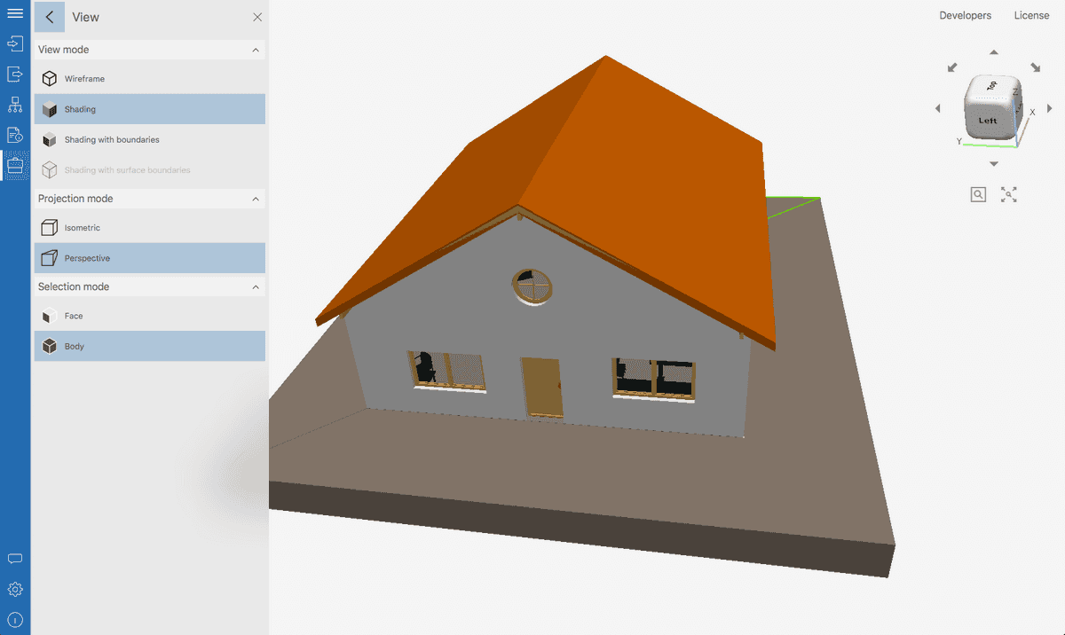
But the same image in perspective view (Fig. 5) will become three-dimensional. An idea about the length of the building and the location of the internal elements will appear.


Working with isometric view in CAD Exchanger Lab
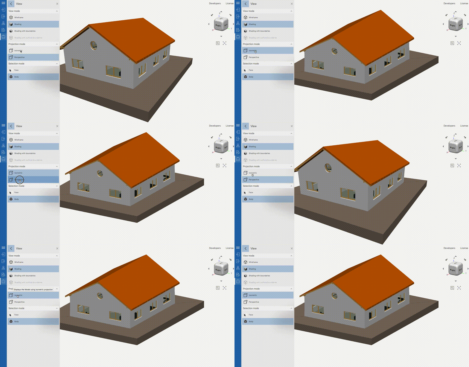
Let's consider the isometric view mode using the example of CAD Exchanger Lab, a professional program for viewing, analyzing and converting 3D-models. CAD Exchanger supports isometric and perspective projections for more than 30 CAD-formats and allows you to switch between in one click.
It support combined view modes: in both perspectives, you can activate shading, wireframe view, meshes, to combine sections in different planes and exploded views. This exceptional flexibility allows the user to quickly and comprehensively analyze 3D-models, build any view to illustrate their arguments and ideas.

View switching settings are located in the side menu. It also features modes such as Shading, Shading with boundaries and Wireframe view (which will be covered in the next posts).

Let's consider switching between isometric and perspective projections using the example of a 3D building model. To make the model more realistic, use the Shading mode without boundary lines.
In the Fig. 8, the building is shown in isometric view. A simplified representation allows you to get a general impression of the model's shape and dimensions.

In the Fig. 9, the building is shown in perspective view. Now it looks much more realistic.

Thus, depending on the problem being solved, you can instantly switch between views and build the most suitable variants.
Conclusions
So, we found out that isometric view when working with 3D-models should be used in that cases:
- when you need to quickly, clearly and accurately depict a simple three-dimensional object;
- when working with particularly complex 3D-models to free up productivity (which does not prevent sometimes switching to perspective view);
- to save time when working with metadata;
- for the design of games and applications based on isometric view.
These recommendations are just a guideline. We hope it will simplify the work for 3D CAD software users. In practice, it can be useful to instantly switch between different views. It is convenient to do this with the help of specialized programs such as CAD Exchanger.
In the next article, we will look at an alternative to isometric view – perspective view. We will determine its advantages, disadvantages and best uses.