Previous part
In 3D CAD software, projections determine the perception of 3D model’s dimensions and proportions. In the first part of the "View modes in 3D CAD" series, we discussed isometric projection. Its alternative is the perspective projection, which we discuss in this post.
What is a perspective view?
A perspective view is a projection with the center located at a finite distance from the projection plane. In the perspective view objects are depicted by lines passing along invisible non-parallel rays connecting in the center of the projection remote from the observer. This distinguishes the perspective view from the isometric one, where lines pass along parallel rays.
The perspective projection is used in cases where the three-dimensionality of an object needs to be rendered more realistically than isometric view allows. In perspective view lines that are parallel in nature appear to intersect in the projected image – for example, if railroads are shown in perspective view, they appear to converge to a single point called a vanishing point.
The perspective view is usually divided into one-point, two-point or three-point perspective, depending on the orientation of the projection plane with respect to the axes of the depicted object (see Fig. 1):
- one-point – a 3D object is created using non-parallel lines converging at one point on the horizon;
- two-point – shows the 3D object from the side, non-parallel lines converge at two points on the horizon;
- three-point – it has two vanishing points on the horizon, but in addition to them it uses a third, vertical perspective point; a three-point perspective is closest to real perception.

Advantages of perspective view
Due to a number of advantages, perspective projection is one of the most commonly used view modes in 3D CAD software.
1. Realism
The objects depicted in perspective projection look about the way we are used to seeing them in reality. This applies equally to rendering the external volume and internal space, the external and internal proportions of the object. Realism makes a perspective view a must in 3D CAD software.
2. Accurate representation of object locations
We can say that this is one of the factors that make the perspective view pretty realistic. Compared to isometric projection, which is great for conveying the simple shapes of a 3D model, but can be misleading as to the location of its individual parts, perspective projection gives a more accurate representation of the location of individual parts.
That's why perspective projection is valued in architectural 3D renderings, where the realism of individual elements is so important.
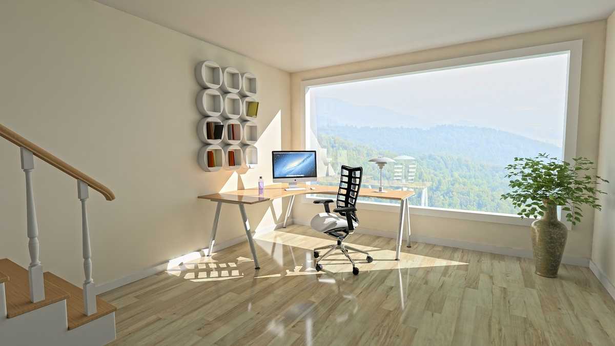
3 . The constancy of 3D
Unlike isometric view, perspective view clearly demonstrates the three-dimensionality of an object, even when looking at the object parallel to one of its axes (that is, at X=0, Y=0, or Z=0).
For example, if we look at Fig. 3, which shows a section of the facade in perspective view, then even with a strictly frontal view (X=0), we can judge the length of the building and the relative position of its internal elements (furniture, doors, etc.).
But as soon as we switch to isometric projection, the internal detail disappears and we get a flat image (Fig. 4).


Disadvantages of perspective view
1. Response speed
Visualization of 3D models, its panning, shifting, rotation, and zooming in and out, especially when it comes to complex assemblies with a degree of subassemblies and parts, requires a significant computing resource.
The amount of calculations depends on the applied view. While in isometric view, objects can be freely rotated and moved without redrawing, which significantly reduces the processor load, in perspective view, it is impossible to reuse the traced elements. With each movement, its proportions will change, which will require new calculations.
That's why realistic perspective projection requires a significant amount of computing power, which can slow down performance on certain computers.
2. Distortion of proportions
Human vision is geometrically close to central projection, on the basis of which perspective images are constructed. Corresponding realism implies a distortion of proportions when objects close to the observer seem too large and distant objects seem too small.
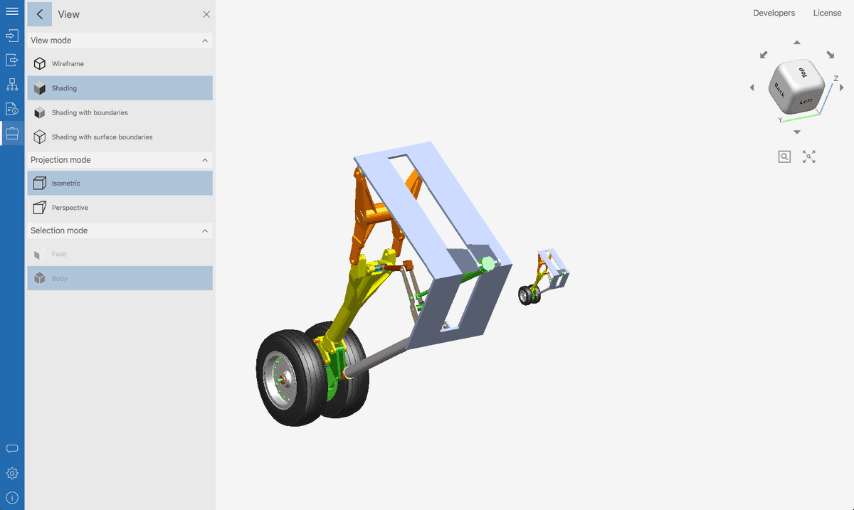
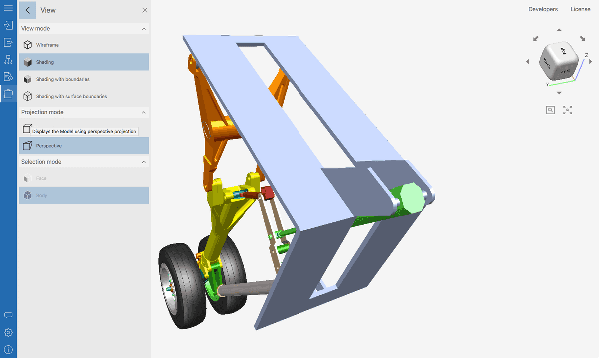
When working with 3D CAD software, this can cause difficulties in some cases, because the perception of the true size of the parts in the assembly can be distorted. The isometric projection allows you to display the correct proportions, although the realism of the image is lost.
As an example, Fig. 5 and 6 show the same 3D model of a landing gear displayed in CAD Exchanger Lab software first in isometric projection (low realism, proportions preserved) and then in perspective projection (high realism, proportions distorted).
3. Ambiguity
Isometric drawing is the best solution when you need to emphasize parallelism or the same size of planes and lines. For example, about a cube depicted in an isometric view, it can be unambiguously stated that it is a cube.
However, as soon as it is placed in a perspective projection, the uniqueness will disappear: the sides of the cube will be distorted by the perspective, and the question of their parallelism will arise. Non-parallel sides can also differ in length. Therefore, we may not have a cube in front of us, but a quadrangular prism.
Working with perspective projection in CAD Exchanger Lab
Let's consider the perspective view mode using the example of CAD Exchanger Lab, a professional software for viewing, analyzing, and converting 3D models. CAD Exchanger Lab supports perspective and isometric views for more than 30 key 3D CAD formats and allows you to switch between them in one click.
It also supports combined view modes: in perspective view, you can simultaneously activate shading or wireframe views, meshes, section planes, and exploded views. This exceptional flexibility allows the user to quickly and comprehensively analyze 3D models, and build any view to illustrate their arguments and ideas.
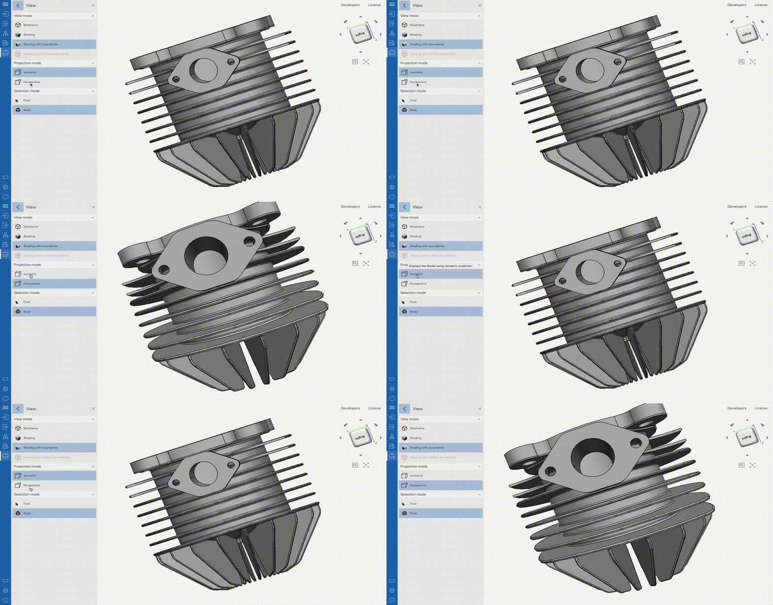
View switching settings are located in the side menu. It also features modes such as Shading, Shading with boundaries and Wireframe view (which will be covered in the next posts).
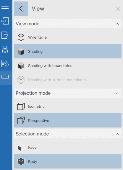
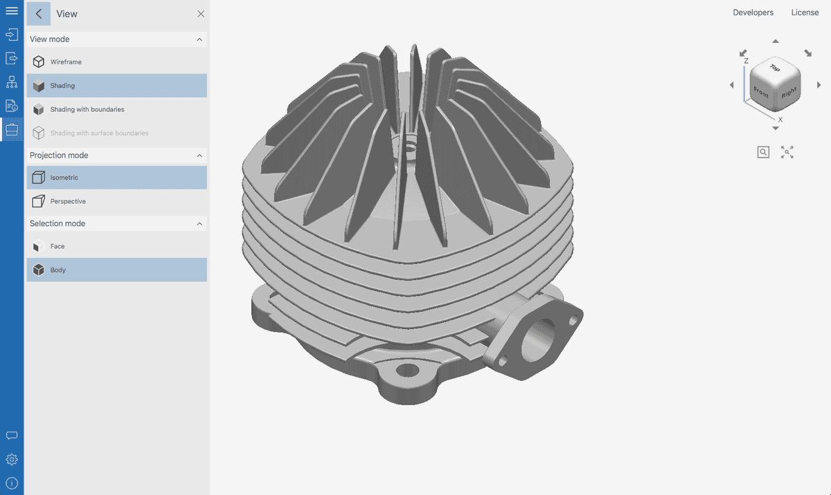
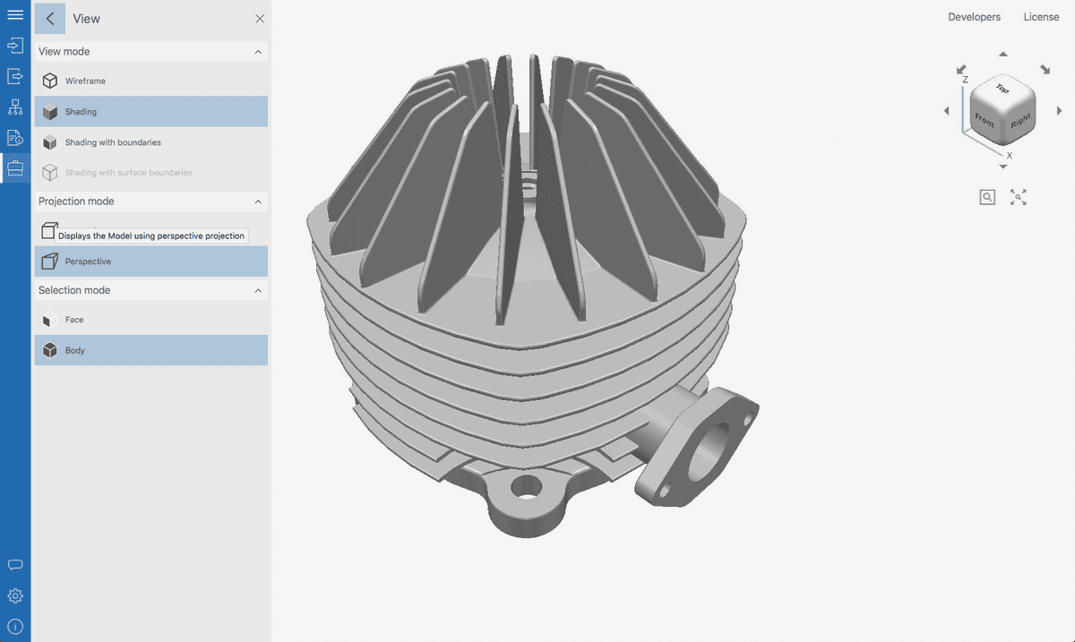
Let's consider switching between perspective and isometric projections using the example of a cylinder head 3D model. To make it more realistic, use the Shading mode without boundary lines.
In the Fig. 9, the head is shown in an isometric view. A simplified representation allows you to get a general impression of the model's shape and dimensions. In the Fig. 10, the model is shown in perspective view. Now it looks much more realistic.
Thus, depending on the problem being solved, you can instantly switch between views and build the most suitable variants.
Summary
So, we found out that the perspective view when working with 3D models should be used in cases when you need:
- to depict a model as realistically as possible;
- to demonstrate the objective location of assemblies and parts in a scene relative to the observer;
- to accurately represent the location of the object in realistic 3D renders.
These recommendations are just a guideline. We hope it will simplify the work for 3D CAD software users. In practice, it can be useful to switch between different views depending on the situation. It is convenient to do this with the help of specialized software such as CAD Exchanger Lab.
So, in parts 1 and 2 we have analyzed the two basic projections used in 3D CAD software. In the next part, we'll move from projections to surface view modes, starting with Shading.
Previous part