Previous parts
What is shading?
We use voxels, meshes, constructive solid geometry (CSG), and boundary representation (B-Rep) to represent 3D data, depending on the situation. You can learn more about these options in the Crash course on CAD data series. Despite their significant differences, there is a common factor that determines the final realism of a 3D object, no matter how it is obtained. This factor is the light source in the image.
For example, we need to create a realistic 3D sphere image. Let’s consider several approaches to solving this task (Fig. 1).
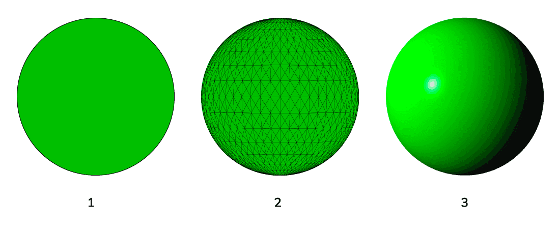
We build an image using a boundary circle in the simplest version of B-Rep (1). Let’s designate the surface with a solid fill. The result is perceived as a filled circle and doesn’t look realistic.
To accentuate the sphericity of the object, we add a tessellation mesh (2). The image becomes much more three-dimensional, but the result is still imperfect.
Finally, we use a light source located to the left of the object instead of a mesh in option (3). Due to the characteristic distribution of light and shadow, this image becomes as three-dimensional and realistic as possible. The circle turns into a sphere.
The method of representing a 3D surface by conditionally directing a light source onto it and a graphical display of the corresponding shadows is shading.
Factors affecting shading in 3D CAD
A shader is a specific software component that performs realistic rendering of light and shadow in 3D CAD programs. It changes the surface color parameters depending on several factors, which, in particular, are:
- lighting type;
- number of light sources;
- the angle between the light source and the surface;
- the distance between the light source and the surface;
- the angle between the surface and the camera;
- distance between illuminated objects;
- surface material;
- interpolation method.
Shading algorithms in shaders of various software are different. They can use different interpolation methods, different sets and combinations of factors, so the illumination of the same model in different programs may vary. Each shading factor is interesting in its own way and deserves detailed consideration. In this article, we will focus on a few of them.
1. Lighting type
The lighting type largely determines the visual effect of shading. The following types apply in particular:
- ambient lighting comes from an omnidirectional source and has a fixed intensity;
- directional lighting comes from a given direction and an infinite distance from the 3D scene;
- point lighting comes from one point and spreads in all directions;
- volumetric lighting comes from a closed space of a small volume and illuminates objects in this space;
- area lighting comes from a small area of one plane;
- spotlighting comes from one point in the shape of a cone.
2. Distance between objects
When there are several objects on the scene, the algorithms of 3D CAD programs must take into account their mutual influence to achieve more realistic shading. The closer objects are to each other, the more they mutually influence the rendering of light and shadow. This process also happens in nature when the sun illuminates two closely spaced objects, then one of them can cast a shadow on the other.
When objects move away from each other, their degree of illumination is aligned, but they can still look different because, depending on the lighting type, the light can fall on them from different angles.
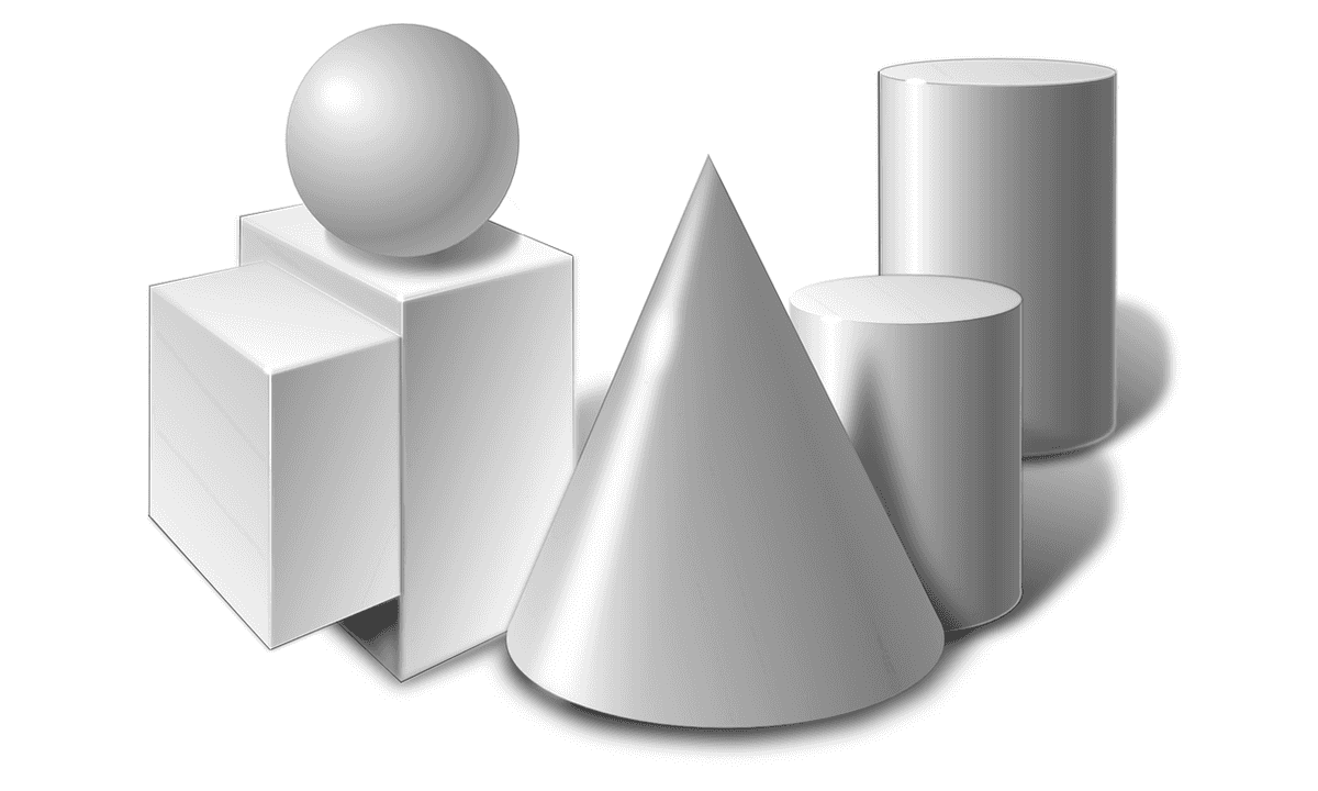
Fig. 2 shows an example that realistically renders the shadows of individual closely spaced figures. You can notice that the shadows of objects in the foreground are the lightest, and those in the background are the darkest. Due to the mutual influence of the location of objects in a group on lighting, the image looks very realistic: you can determine the approximate location of the light source, each figure has a pronounced three-dimensionality, and there is an effect of space and depth.
The figures also cast shadows, indicating the plane on which they stand. Although shadow casting is not always used in 3D CAD programs, this example perfectly shows how objects affect each other's lighting and why shading algorithms take into account the distance factor between objects.
3. Interpolation method
For an ideal calculation of brightness in shading, theoretically, you need to calculate normals to an infinite number of surface points. But since 3D models are characterized by a polygon mesh with a limited number of points, various interpolation methods are used. They allow calculating intermediate normal values based on a limited set of points.
These methods include Gouraud shading, flat shading, smooth shading, and data structure shading. We will not consider them in detail. It is only worth noting that although none of the interpolation methods in shading is 100% perfect, and visual anomalies are possible, these methods provide a sufficiently high shading accuracy for precision work with 3D models.
Advantages and disadvantages
In this article, we discussed shading, one of the surface display modes. It is enabled by default in the majority of CAD software, so let's sum up the pros and cons of this mode.
The pros include:
- realism is no doubt the main advantage of shading;
- the ability to simulate multiple sources and lighting conditions.
The cons include:
- processor load – shading can slow down work with a 3D model, especially if you open a complex model on a computer with low performance;
- visual anomalies are possible in rare cases, for example, on T-shaped forms;
- opacity manifests itself when the task is to show the internal structure of a 3D model.
Shading mode in CAD Exchanger Lab
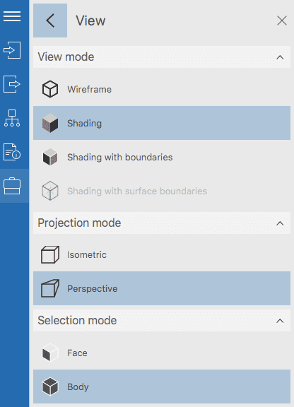
Let's consider how we can use the shading mode for work with 3D models using the example of CAD Exchanger Lab. The program is designed for professional analysis, viewing, and conversion of 3D models among more than 30 CAD formats. The following viewing modes are available:
- Wireframe view mode, in which lines and points indicate the 3D model;
- Shading;
- Shading with boundaries is the combination of shading and wireframe. Lines supplement shading for a visual indication of external borders;
- Shading with surface boundaries is a combination of shading and automatically recognized surface boundaries (works only for meshes).
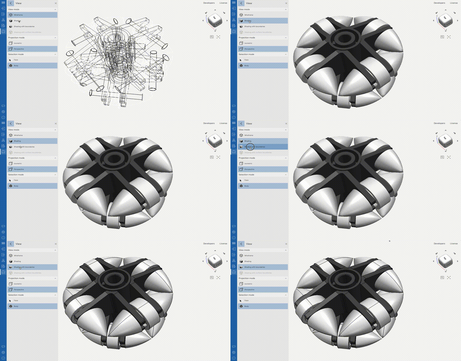
View switching settings are located in the side menu. Switching happens in one click.
Shading is available for all view modes. It works in isometric and perspective projections, applied to meshes, sections, and exploded views, as well as their combinations.
Let's look at the use of shading to represent the surfaces of 3D models using an omnidirectional wheel as an example.
Fig. 5 shows the model in the Wireframe mode. Realism in this mode is minimal, but you can see the internal structure of the wheel. Analysis of the internal structure is also possible in Shading mode, but with the use of auxiliary tools such as sections, exploded views, and disabling individual components of the assembly.
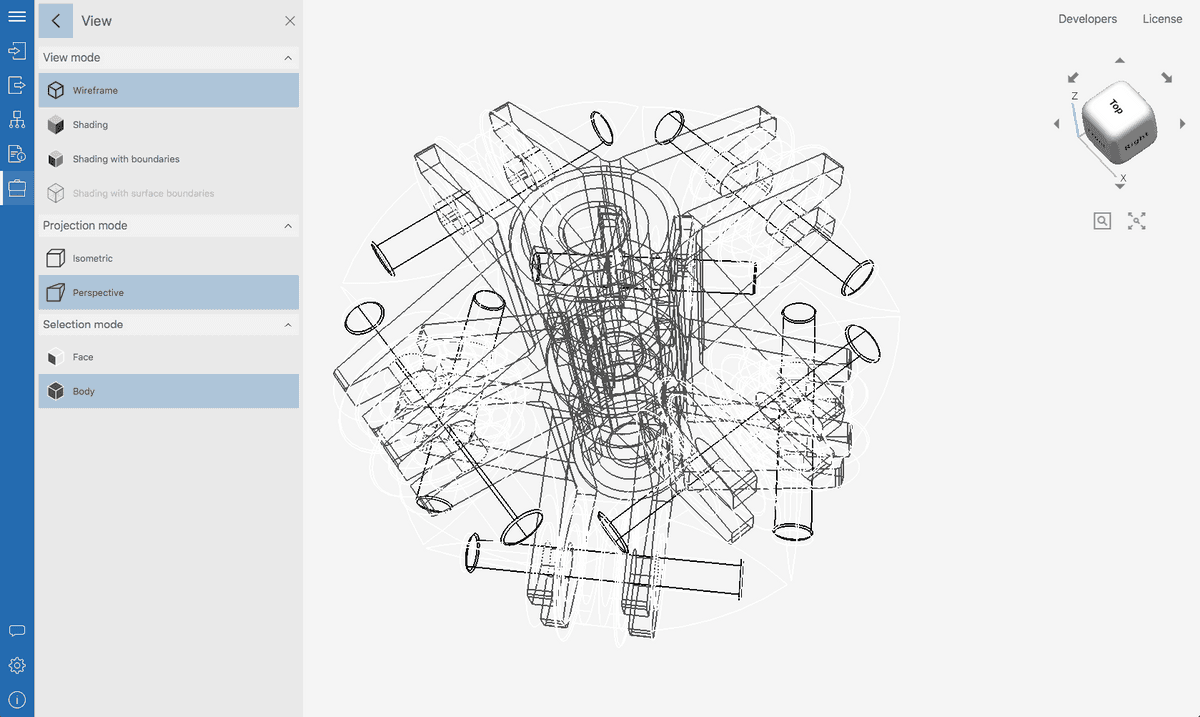
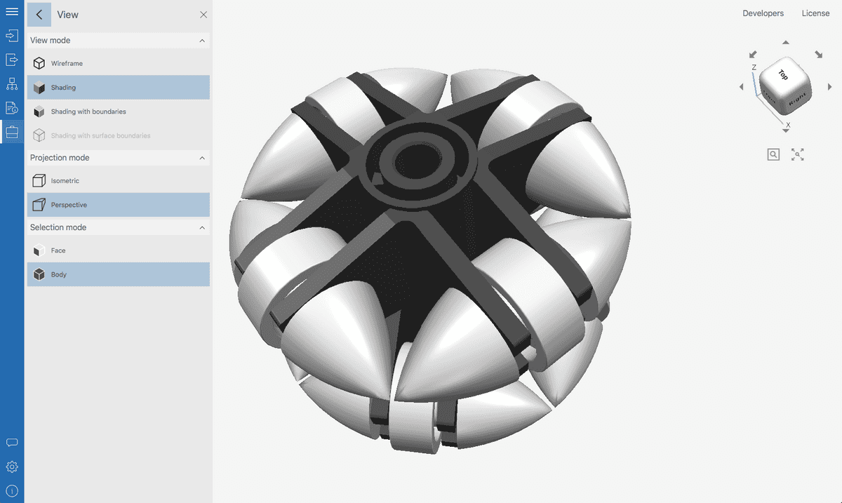
Fig. 6 shows a model in the “classic” Shading mode with maximum realism. There is a perspective projection to achieve an even greater effect of realism.
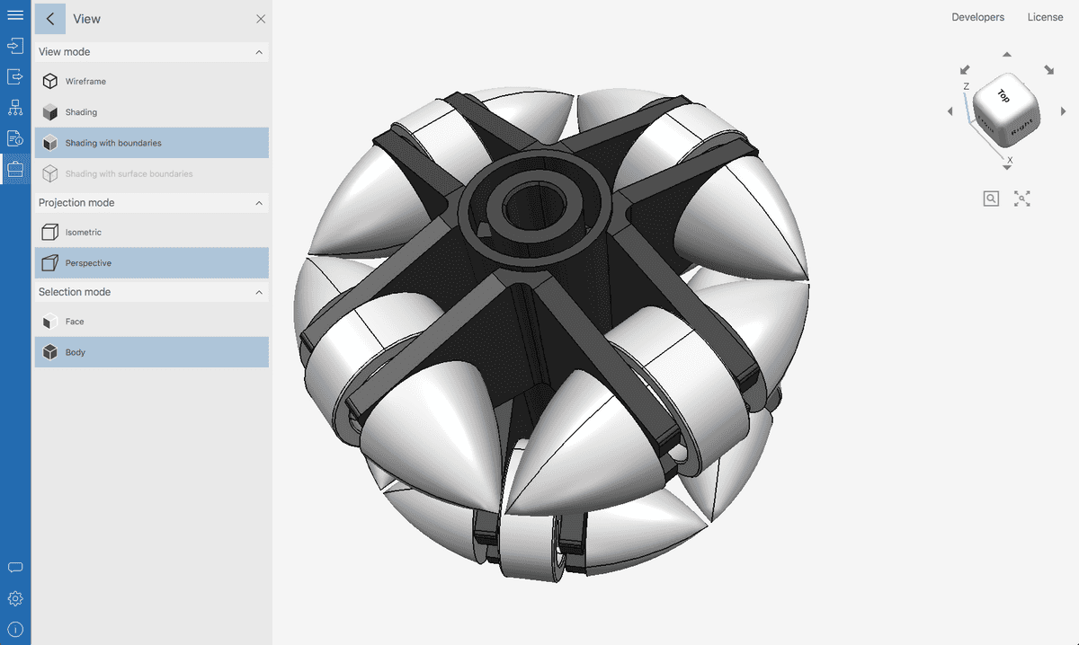
Finally, Fig. 7 shows the model in the combined Shading with boundaries mode, where the Shading and Wireframe modes are combined. This mode limits realism but can make it easier to perceive the shapes of individual parts of the model.
Conclusions
So, we found out that the Shading mode is the main one for rendering 3D models, due to its high realism and the ability to reproduce a variety of lighting conditions. Working with light and shadow in 3D CAD programs requires taking into account many factors and a significant computational resource, but this is justified. In the next part of the series, we will look at an alternative to shading, the Wireframe mode.
Previous parts