3D file import workflow
After very brief and high-level introduction of CAD Exchanger SDK let me offers some insights into SDK mechanics. Hopefully this will be not just curious but mainly useful to understand with respect to your usage of SDK.
Importer workflow
Overwhelming majority of our users start with integration of reading CAD files (STEP, JT, Parasolid, ACIS or whatever) into their app. This is pretty straightforward and is given in every relevant example:
#include <cadex/STEP_Reader.hxx>

cadex::STEP_Reader aReader; //STEP reader
cadex::ModelData_Model aModel; //document encapsulating data
if (aReader.ReadFile (theFileName) && aReader.Transfer (aModel)) {
    ExploreDataContents (aModel); //do specific stuff
}
Now let’s have a closer look at the line where aReader object is used. There are two methods invoked – ReadFile() and Transfer(). Both are defined in the base class cadex::Base_Reader and do the following:
- ReadFile() – parses the input file contents into memory;
- Transfer() – converts in-memory representation into ModelData_Model object.
The following diagram reflects these steps:

File model
The file model is essentially a format-specific container that provides a graph of objects representing format-specific entities encountered in the given file. C++ classes that represent file model are close counterparts of the file format entities and typically contain same data items and cross-references.
For instance, here is an excerpt of an ACIS file (having a .sat extension)
“edge $-1 $35 $36 $17 $37 0 #”
“edge $-1 $36 $80 $33 $81 0 #”
…
“straight-curve $-1 50 -40 0 0 -0 1 F -81 F 61 #”
According to the ACIS file format this should be interpreted as if edge N contains two vertices (start and end) with indices 35 and 36, parent co-edge 17 and curve 17. Likewise, edge N+1 has vertices 36 and 80, co-edge 33 and curve 81.
These two edges share the same vertex 36 (the former edge as its end and the latter as its start), so the file model object will contain C++ objects representing ACIS edges that would refer in memory to the same C++ object representing an ACIS vertex.
The curve 17 is a line (ACIS type “straight”) which has origin of (50,-40,0) and unit vector (0,0,1).
File model encapsulates format specificity and is not exposed into public SDK API, as the user essentially has no need to deal with it. The instance of file model remains under the cover and is passed inside SDK between ReadFile() and Transfer() methods.
ReadFile() creates and populates a file model object using either a disk file or an arbitrary std::stream as a data source. Version 3.3 also introduced even more flexible API to support cloud-based scenarios.
Conversion phase
Once the file model has been populated, it can be converted to an instance of the ModelData_Model.
This happens by visiting the graph of objects and applying converters to each specific data type. For instance, in the above ACIS example the converter will create instances of cadex::ModelData_Edge for each ACIS edge, ModelData_Vertex for each vertex and ModelData_Line for ACIS straight.
The converter will also preserve sharing of objects, i.e. two resulting Model_Edge instances will refer to the same instance of ModelData_Vertex which resulted from original ACIS vertex shared by two ACIS edges.
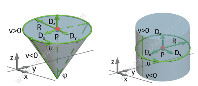
Each format often has own specificities in representing data which are taken into account when converting to resulting object. For instance, ACIS represents both cone and cylinders via base ellipse and angle sine and cosine, whereas CAD Exchanger has distinct types for these surfaces and uses axis placement and a radius, and semi-angle for cone.

Parasolid V-parametrizes a conical surface along the height, whereas CAD Exchanger – along the side generatrix. Parasolid does not contain vertex parameters on the edge curve where CAD Exchanger does and so on.
So there is a lot to be done during this conversion phase to map and adapt data. Additionally quite often 3D data has to be ‘healed’ to resolve issues of poor quality. This includes large gaps between edge vertices, inconsistent 3D and 2D curve representations, mismatched face loop orientations, missing seam and degenerated edges and what not.
Performance considerations
Depending on format specificities and particular 3D models, time between the two steps can vary. In general, the Transfer() phase takes more time comparing to ReadFile(). In some format-specific cases parsing phase (ReadFile()) may read contents directly into ModelData_Model, so in that case Transfer() is effectively a ‘no-op’.
Given significant distinctions in data representations between CAD formats and thus necessity to reliably convert and to heal data, we have been paying significant attention to performance in order to provide best possible user experience.
This is where my own passion for parallel (primarily multi-threaded) computations applied in the first place. We spread this passion and sense of challenge throughout the team. This passion regularly makes us to have a spontaneous brainstorming sessions on how we could do better. When an ‘a-ha’ moment results in something really cool with highly promising outcome we try to see if this idea can be converted into a patentable know-how. At the moment we proudly own two patents with more ideas in the pipeline.
Importing large assemblies
Hopefully the above sections managed to provide a general overview on how the import workflow executes.
That was essentially about how import works in typical use case. However there is much more to this, especially when it comes to importing large assemblies with numerous parts inside, each with several representations (B-Rep and multiple polygonal representations, aka levels of details or LODs).
In this next series I will share some insights how such complex files could be imported more efficiently into user’s application with the help of CAD Exchanger SDK. Stay tuned!