Previous parts
What is a wireframe model?
A wireframe model is a 3D model consisting of lines and vertices only. Wireframe representation can be considered a special case of a boundary representation (B-Rep) with "disabled" or invisible outer and inner surfaces. For example, Fig. 1 shows the B-Rep cooler model in the shading mode. Fig. 2 shows the same model in the wireframe mode.
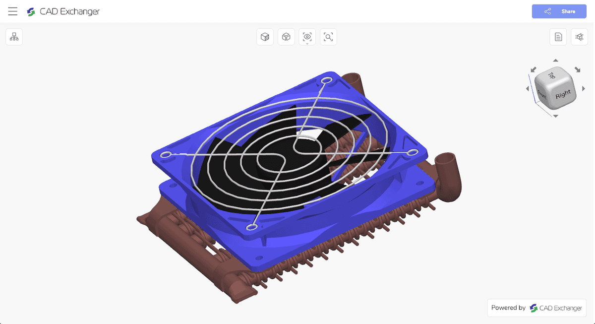
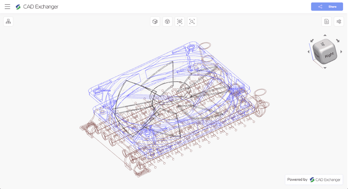
As you can see, the wireframe displays three-dimensionality with a low degree of realism. In the absence of surfaces, the accuracy of rendering the nuances of the model depends on the number of edges. If the properties of the surfaces are unknown, then it is impossible to restore these surfaces from the 3D wireframe model since you need to know the normals to an infinite number of their points. In other words, there can be an infinite number of topologically non-equivalent three-dimensional bodies with the same framework.
But if the wireframe view displays the three-dimensionality of an object in such a limited way, then why is it used in 3D CAD programs? To answer this question, let's look at the pros and cons of a 3D wireframe model.
Pros of the 3D wireframe view
1. Performance. The absence of surfaces reduces the load on the processor and requires less memory. This allows you to work comfortably with complex 3D wireframe models, even on computers with low performance.
2. “X-Ray View”. It provides a quick understanding of the model internal structure and the relationship between the parts in the assembly. Although, this is true only for simple models. The more complex the model, the more visually difficult it is to analyze its design in the wireframe mode.
To analyze complex models, you can use such options as enable/disable individual assembly elements, use section views, exploded views, or their combination in the shading mode.
3. Design simplicity. In some cases, sketching a 3D model from scratch can be easier done in the wireframe mode. After all, you do not need to devote time to the creation and design of surfaces. You can ignore surfaces to show the design idea
4. Intellectual Property Protection. As mentioned above, it is possible to restore body surfaces from a wireframe 3D model only if you know their original properties. This allows you to use wireframe as a "demo mode", hiding the actual view of the assembly or a part from prying eyes.
Cons of the 3D wireframe view
1. Ambiguity. It can be difficult or even impossible to distinguish between visible and invisible faces and assess the location of lines relative to the observer in a wireframe 3D model since they are all in the same plane. To partially compensate for this shortcoming, the program can assign different colors to different parts and their faces in the assembly (see Fig. 2).
2. Eyestrain. On the one hand, this is a consequence of ambiguity, which increases with the complexity of the model. On the other hand, a purely visual factor matters: the simultaneous intersection of many lines creates an excessive visual load.
3. Loss of detail. It is impossible to fully display curved faces (for example, on cylindrical surfaces). Imaginary edges, which are created at the discretion of the designer, allow getting around this problem in an extremely limited way.
4. Loss of clear interaction. It can be difficult or even impossible to determine how assembly parts are connected and interact with each other in a wireframe 3D model. This is a consequence of all the previous points.
Usage with B-Rep and meshes
3D CAD software uses two main types of data representation: boundary (B-Rep) and polygonal (mesh). If you apply a wireframe to the B-Rep model with curved faces, they will be lost. The visually perceived form of the model will undergo strong changes with all the ensuing disadvantages listed in the previous section.
If you apply a wireframe to the same model in polygon representation, its visually perceived shape will remain unchanged. Since the detailing of the surfaces was already limited to a certain level of detail (LOD) at the tessellation stage, the faces of the wireframe will coincide with the mesh lines. For this reason, when activating the wireframe mode on polygonal models, the user will see a transparent mesh (Fig. 3), which he may not notice in the shading mode, active by default (Fig. 4).
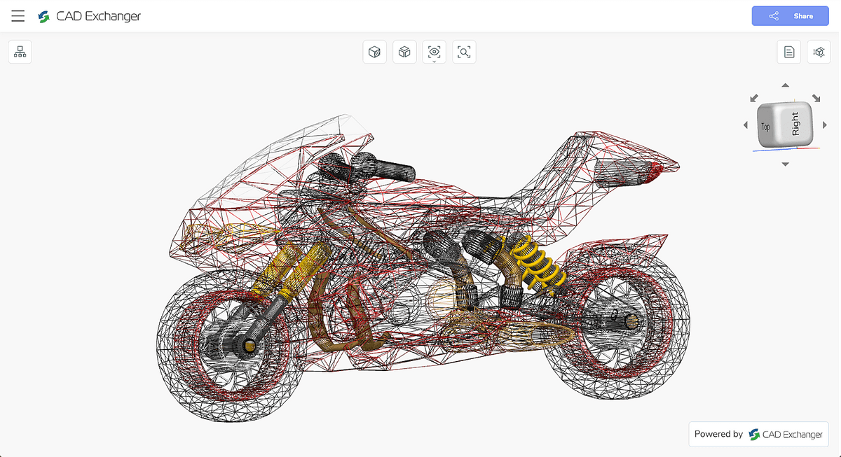
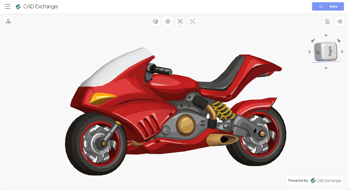
In addition, you can combine the wireframe mode with the shading mode in 3D CAD programs. Let's consider this special case further using the CAD Exchanger Lab software as an example.
Wireframe view in CAD Exchanger Lab
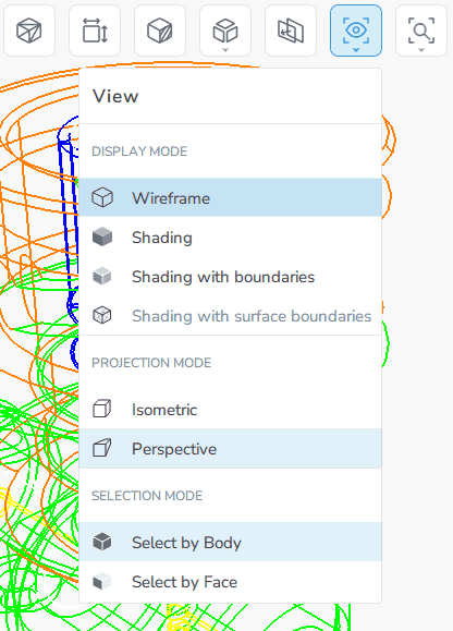
CAD Exchanger Lab is designed for professional analysis, viewing, and conversion of 3D models among more than 30 CAD formats. The following viewing modes are available:
- Wireframe;
- Shading;
- Shading with boundaries. This is a combination of shading and wireframe. Shading is supplemented with lines to visually more clearly indicate the outer boundaries;
- Shading with surface boundaries. This is a combination of shading and surface boundaries restored from a polygonal model. The mode is active only for polygonal models.
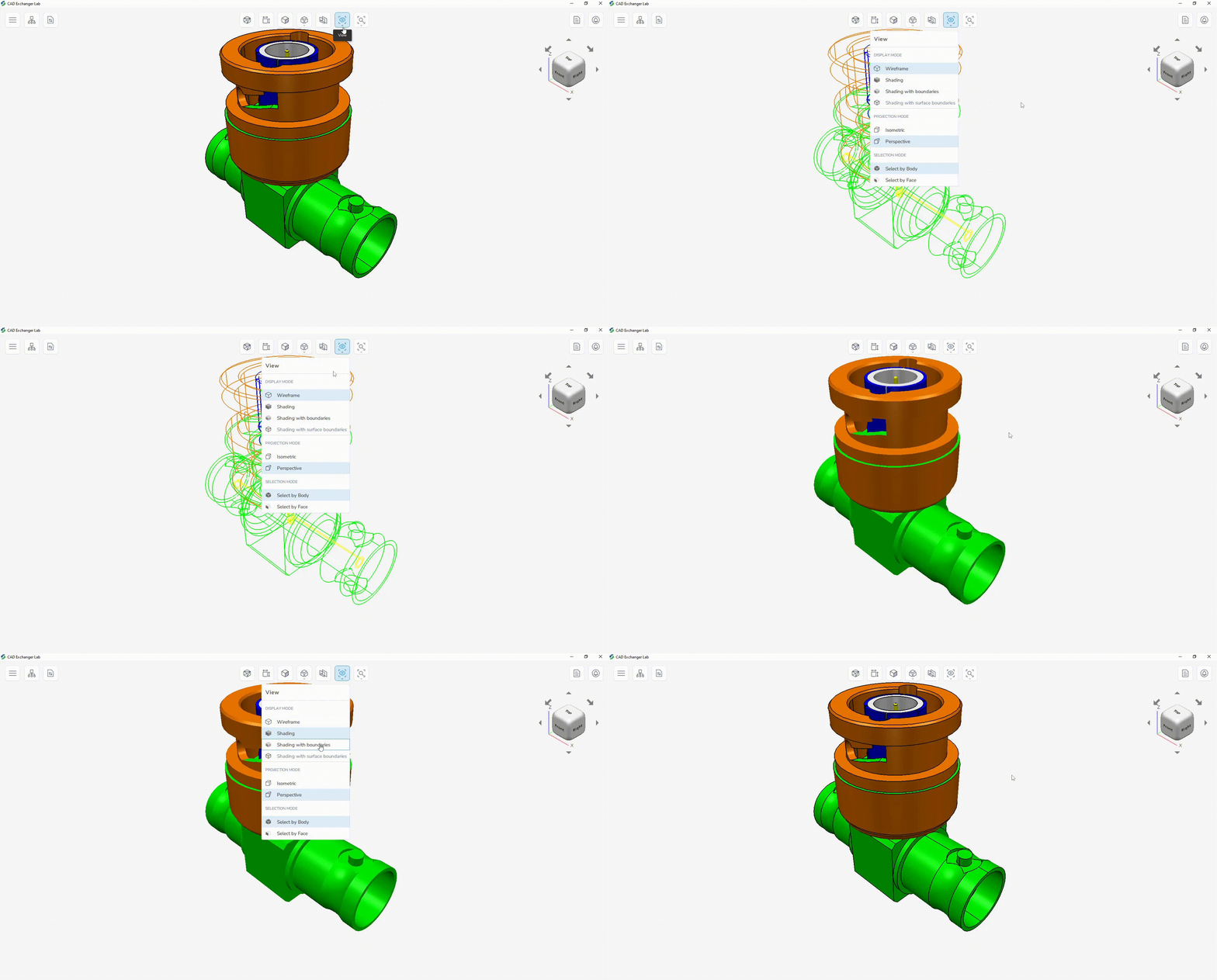
View switching settings are located in the top menu. Switching happens in one click.
You can combine wireframe with other view modes: it works in isometric and perspective views and is combined with shading, section, exploded views, and their combinations.
Consider using a wireframe view using a 3D valve model as an example.
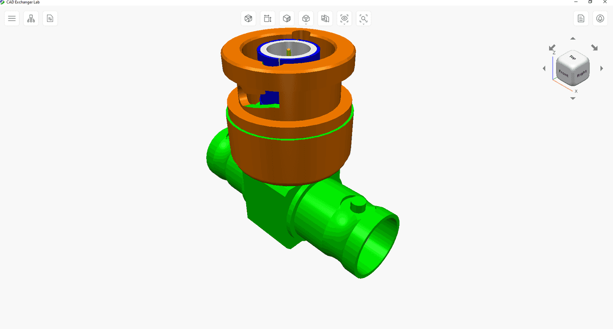
By default, this 3D model opens in the shading mode as the most realistic representation of three-dimensionality (Fig. 7). Analysis of the internals in the shading mode is possible with aids such as sections, exploded views, and disabling individual components of the assembly.
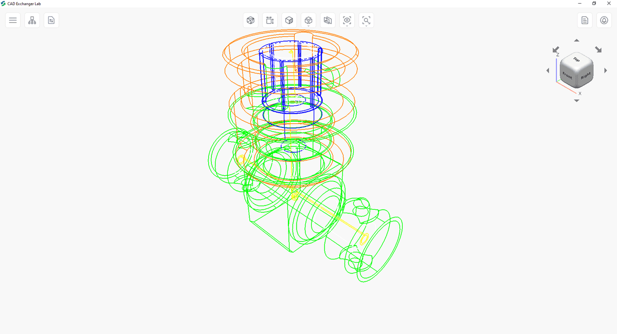
However, if you switch the model to the wireframe mode (Fig. 8), you can instantly evaluate the internals of the valve. You will see a stem, a longitudinal channel, a control mechanism, and other elements. Of course, we lose three-dimensionality in this mode, but in return, we get an “X-ray view” that is more comfortable for analyzing the internal structure.
Finally, you can use the shading with boundaries mode, where shading and wireframe are combined (Fig. 9). This mode is no longer suitable for instant analysis of the internal structure, but is one of the most visually illustrative. It is suitable for cases where you need to clearly define all the faces of the model. You can't achieve this in shading mode, as the different faces are illuminated differently and can merge with each other.
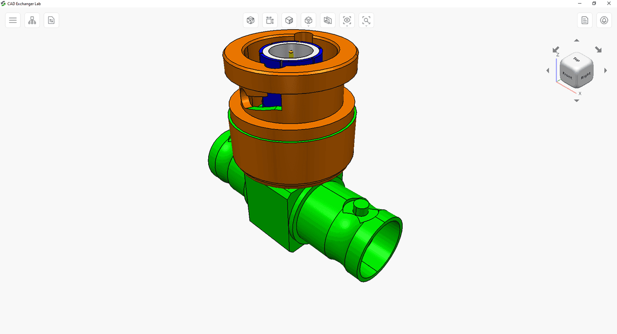
It may be necessary to repeatedly switch between wireframe and shading in practice, so CAD Exchanger Lab provides a top menu for quickly activating the desired mode.
Summary
So, we found out that the wireframe view for work with 3D models is useful in the following cases:
- when working with complex 3D models to increase productivity;
- when it is necessary to display a three-dimensional object, ignoring its surfaces at the initial stage or in the absence of data on surfaces;
- for quick analysis of the internal structure of the model;
- to protect intellectual property;
- for accurate visual rendering of faces in combination with the shading mode;
In the 5th and 6th parts of the series, we will analyze two other popular modes for a detailed analysis of the internal structure of the models. We are going to define the pros and cons of section and exploded view, and their best uses.