Previous parts
In the previous parts, we discussed isometric, perspective, shading, and wireframe display and projection modes. Now it’s time to move on to the one view that can give us a real insight into any 3D model.
What is a sectional view?
A sectional view is an orthographic projection of the object with one or a few cutting plane lines to reveal its hidden or internal features. It shows all parts, including the insides and some parts that are difficult to see. A section view enhances the visualization of the model and simplifies dimensioning.
You can use this view type to look at and transform the internal or hidden parts of 3D models. It comes in when you need to divide the model into smaller pieces and understand the structure as a whole and the major relationships between spaces.
Section planes and other terms
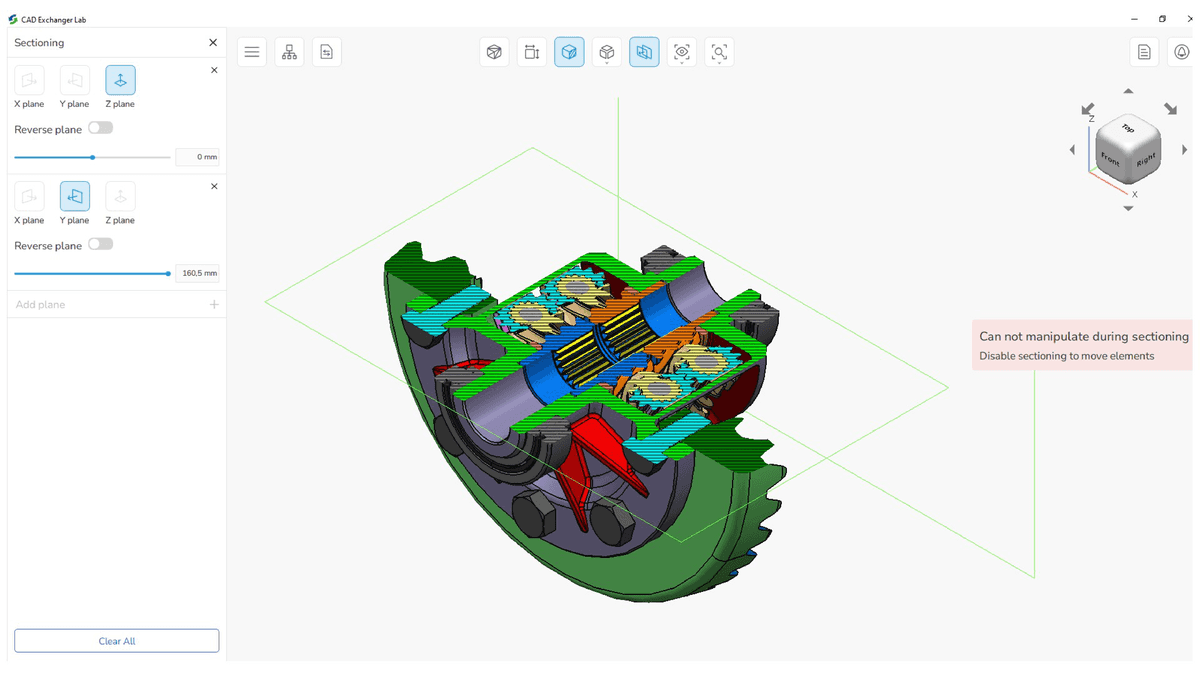
Speaking of the sectional view, it is crucial to mention a few terms that are widely used.
- a section plane is a particular section of a model that looks like somebody were to cut it.
- a cutting plane line is a line that runs through a model and we can see a certain interior view. It can be a thick hidden or phantom line.
- arrows on the cutting plane line are an indication of gaze direction when you look at the section view.
- a sectional drawing is a technical drawing that shows interior parts and features using sectional views.
- section or hatching lines specify materials in sections.
Which type of sections is used for 3D models ?
There are a few common types of sections: full, half, offset, broken out, revolved, and removed. When you work in 3D programs, a full section is more than enough, because you can rotate the model as you wish.
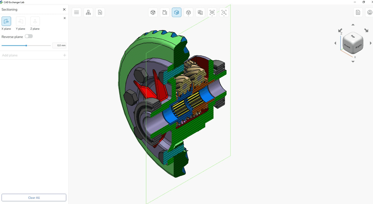
The full section is one of the popular views that shows the entire object looks when an imaginary line passes through it. Simply speaking, this line divides the object into two pieces from one end or side to the other. In 3D programs, you can use the slider to move the section plane line along the axis. Accordingly, there is no need for different types of sections, because we can analyze the model quickly even without them.
Advantages and disadvantages of section view
Sectional views are crucially important in the analysis of 3D models, so let's take a detailed look at the pros and cons.
The pros include:
- improvement of the visualization and clarification of designs. For example, you can hide certain sections of the 3D house model and look at load-bearing walls that are typically inaccessible to view.
- revealing hidden features of parts. Using a sectional view, you can control the divisible, indivisible parts, and the assemblies of any model.
- facilitation of the dimensioning of models. Often the section helps to determine the parameters of the object. For example, you can determine the size of the gating system based on the cross-sectional area of the feeders.
- flexible control over the display of the model. The cutting plane line divides the model or any part in the place where it is necessary to reveal its shape. Fig. 3 shows a cross-section of only one part of the torsen differential, not the entire solid model.
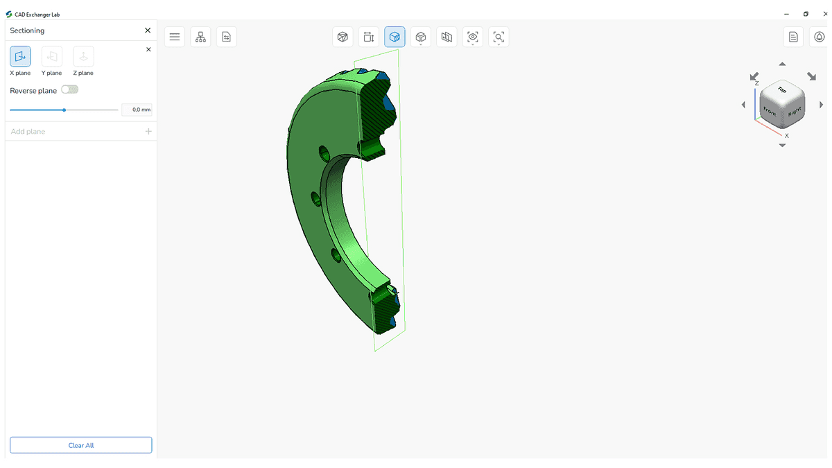
- elimination of design errors. Thanks to the sectional view, it is possible to assess the rationality of the adopted engineering decisions, which leads to a reduction in design miscalculations, additional communications, and the emergence of other difficulties.
The cons include:
- very thin sections can not be hatched. For example, there are no hatching lines on gaskets or seals.
- symbols, rules for hatching lines and displaying materials in sections may vary to some extent in different companies. Therefore, the issue of compatibility may arise, and it will take time for the correct design of the sections.
Advantages of section view over other methods of analyzing 3D models
There are a few ways to analyze the design of complex 3D models: enable/disable individual assembly elements, use wireframe, exploded, or section view. Section view allows you to perform the most detailed and accurate analysis of individual parts, and let's see why.
The first and primitive way to analyze any part of the 3D model is to enable or disable individual elements in the assembly that block other parts that you want to explore. But the point is that an assembly can include thousands of details, and this would affect other assemblies where generic elements are used. In many cases, this method is very time-consuming and inconvenient.
The second way is to use a wireframe mode. Using this mode, we make the model transparent, and we can see how it works inside. There is only one problem: all lines are visible at the same time, so it's easy to get confused. The more complex the model, the more visually difficult it is for us to analyze its design. Besides, prolonged viewing of complex models in the wireframe view can cause eyestrain.
The third way is to resort to the exploded view that allows you to see all the elements separately. Its disadvantage is that the parts are displaced relative to each other during the explosion, so sometimes it is difficult to understand their accurate location. Although, it is much more convenient for detailed analysis than the two methods above.
As for the section view, this mode allows you to make a section that will immediately display the structure of the model exactly in the chosen area. It eliminates the disadvantages of the first three methods and significantly saves time.
How to create sectional views in CAD Exchanger?
Let’s move on and see sectional views on 3D models using CAD Exchanger Lab. With this app, you can view, analyze and convert models in more than 30 CAD formats. There you can flexibly build models in 3 planes X, Y, Z, and even combine sections in these planes. Moreover, you can use a reverse plan in case you need to see part of the model from an opposite side.
Switching settings are located in the side menu.
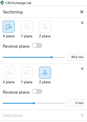
You can change the plane by moving the slider or by entering a specific numeric value.
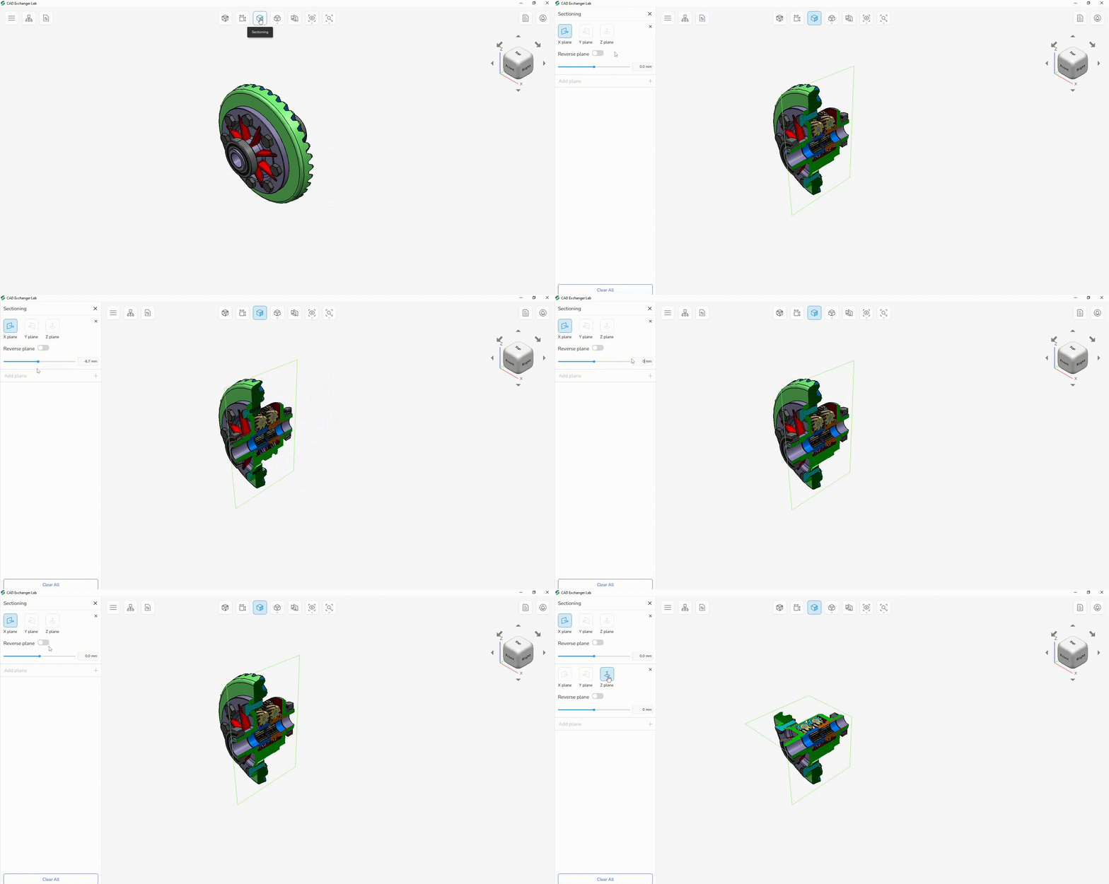
For example, let's take look at the full section torsen differential. If you want to remove more parts of the model, add one more plane and use the slider to achieve the necessary result. You can combine in 3 planes at the same time! It is also possible to combine sectioning with different display modes such as shading, wireframe, or exploded to get a more accurate picture of the model. To do this you need to adjust section planes and choose the desired view on the top menu.
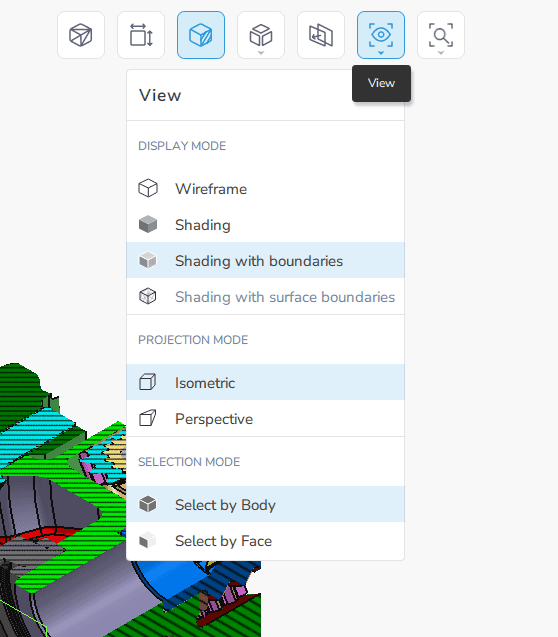
For example, Fig. 7 shows a quarter of the torsen differential in an exploded view.
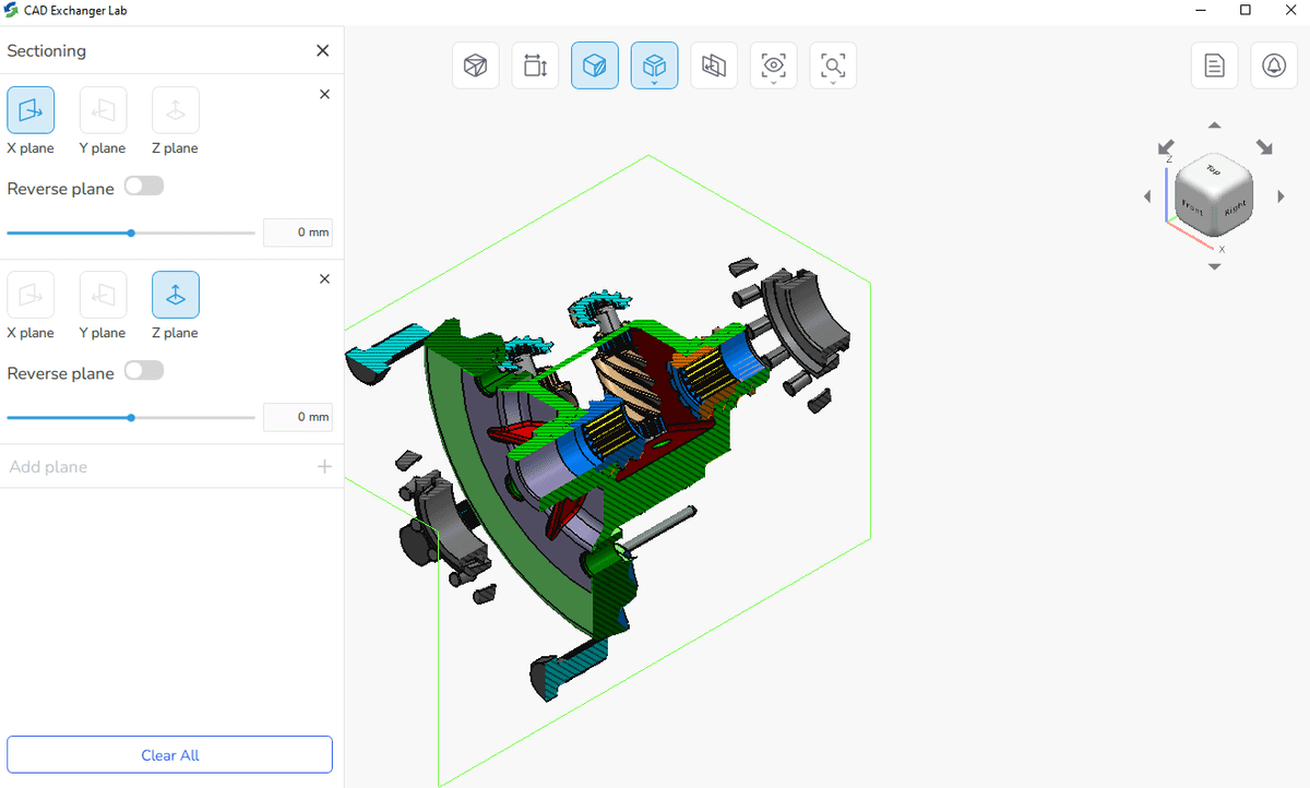
Thus, depending on the task, you can use different section planes to go deep into the details of the model, its material and components.
Here's a short video showing how to create sectional views in CAD Exchanger:
Summary
In this article, we talked about the section view definition and looked at several examples of its use. It makes sense to use this type of view in the following cases:
- to enhance the visualization of the model and simplify dimensioning;
- to see internal details, understand the construction methods and materials;
- to assess the rationality of the adopted engineering decisions.
These recommendations are just a guideline. We hope it will simplify the work for 3D CAD software users. In practice, it can be useful to switch between different views depending on the situation. It is convenient to do this with the help of specialized software such as CAD Exchanger Lab.
In the next part, we will continue to explore view modes and are going to study an exploded view in detail.
Previous parts