Conversion from Open CASCADE to IAM is not supported yet :(
Learn more
Open CASCADE
In solid modeling and computer-aided design, boundary representation—often abbreviated as B-rep or BREP—is a method for representing shapes using the limits. A solid is represented as a collection of connected surface elements, the boundary between solid and non-solid.
Boundary representation of models are composed of two parts: topology and geometry (surfaces, curves and points). The main topological items are: faces, edges and vertices. A face is a bounded portion of a surface; an edge is a bounded piece of a curve and a vertex lies at a point. Other elements are the shell (a set of connected faces), the loop (a circuit of edges bounding a face) and loop-edge links (also known as winged edge links or half-edges) which are used to create the edge circuits. The edges are like the edges of a table, bounding a surface portion.
Compared to the constructive solid geometry (CSG) representation, which uses only primitive objects and Boolean operations to combine them, boundary representation is more flexible and has a much richer operation set. In addition to the Boolean operations, B-rep has extrusion (or sweeping), chamfer, blending, drafting, shelling, tweaking and other operations which make use of these.
IAM
An IAM file is an assembly model created with Inventor CAD and engineering software by Autodesk.
The IAM format comprises parts and subassemblies linked through assembly relationships. A subassembly in an IAM file is a self-contained unit with its collection of parts.
The .iam extension of an Autodesk Inventor Assembly Data File can be viewed using the following software: Autodesk Inventor / Inventor View, and Spaceclaim Engineer software. Autodesk Viewer web application and Fusion 360 integrated CAD / CAM / CAE software environment can import and render an assembly model created with Inventor.
From Our Blog
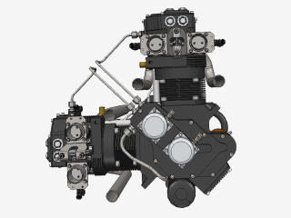
Everything you need to know about CAD file formats
A CAD file is an output of a CAD software, containing key information about the designed object: its geometry and topology representation, 3D model hierarchy, metadata, and visual attributes depending on the format of the file.
Read more
Integration with UNIGINE engine
This article explores the integration possibilities with the UNIGINE engine, a powerhouse in the realm of virtual simulation and game development. Learn how it can be used in applications built with the UNIGINE engine to import CAD and 3D models.
Read more
Manufacturing Toolkit and Web Toolkit enhancements, Unity performance optimization, renaming and rotating SDK examples in release 3.24.0
Explore the wall thickness at a specific point on a surface, enjoy four times faster Unity objects performance, and check out renaming and rotating examples in SDK.
Read more