Conversion from IFC to CATIA V5 is not supported yet :(
Learn more
IFC
IFC, an open file format widely embraced in the AEC industry, enables information exchange and collaboration throughout the project lifecycle between diverse software applications. It contains detailed and structured data about building and construction elements, such as walls, floors, windows, etc.
Supported versions
Here are the currently supported versions by CAD Exchanger:
IFC2X3 is commonly used in various industries, allowing you to easily exchange data among software platforms.
IFC4 (up to 4.3) introduces new data schemas and refinements to further enhance interoperability and data exchange reliability.
Support of IFC in CAD Exchanger
CAD Exchanger can import IFC files of versions 2X3 and 4 (up to 4.3) and export IFC files of version 2X3. Such support includes:
- B-rep and polygonal representations;
- assembly structure;
- names;
- user-defined properties;
- colors;
- layers.
Follow this link to check out all the CAD Exchanger products.
Pros of the format
Variety of entities
One of the key advantages of the IFC format is its extensive support for entities specific to the architecture and construction domain. It provides a comprehensive set of predefined entities that capture the elements and components found in projects. These entities range from fundamental elements like walls, floors, and doors to more specific elements such as windows, stairs, and HVAC systems.
Comprehensive Data Representation
IFC offers a wide range of entities and attributes that allow for the representation of design information, construction sequencing, cost estimation, project scheduling, facility management, and more. It enables rich information exchange, facilitating better communication and understanding among project stakeholders. It allows for more accurate analysis, visualization, and simulation, leading to improved decision-making throughout the project lifecycle.
Cons of the format
B-Rep limitations
Between IFC 2x3 and IFC 4, the former has certain limitations in terms of its range of geometric representations. IFC 2x3 does not support B-rep and typically represents objects with the use of polyhedra, sweeps, or basic Constructive Solid Geometry (CSG) shapes. In contrast, IFC 4 removes this limitation by offering support for full B-rep shapes. However, it is worth noting that the existing geometric representations provided by IFC 2x3 are often sufficient for many applications.
Data sharing issue
IFC has its own structure, optimized for buildings, so it provides technical possibilities for sharing data, primarily at the level of geometry. Transferring generic CAD models with shared parts and subassemblies between various assemblies to the IFC format can be challenging due to the inherent limitations of the format.
This conceptual rearrangement can involve mapping the non-BIM data to the appropriate IFC entity or property, ensuring that the relevant information is preserved and accurately represented. It may require additional effort and careful consideration to properly structure and integrate the non-BIM data within the IFC format.
FAQ
What are the benefits of using IFC format?
This format offers advantages such as data consistency and the ability to exchange rich building information across a wide range of software platforms.
Which industries use IFC format?
This format is predominantly used in the AEC industry. This encompasses a wide range of professionals and organizations, including architects, structural engineers, MEP (mechanical, electrical, plumbing) consultants, contractors, facility managers, and more. Additionally, industries related to building operations and maintenance, such as facility management, can also benefit from the IFC format's ability to store and share building information effectively.
How to open an IFC file?
To open this file, you will need a compatible software application, for example, CAD Exchanger Lab. Launch the software and navigate to the 'New file' option. Browse your computer's directories and locate the IFC file you want to open. Then select the file and click "Open". Once the import process is complete, the file should be loaded into the software, allowing you to view and interact with the 3D model and associated data.
Does IFC format support the representation of complex building elements?
Yes, the format provides support for a wide range of building elements, from basic components like walls and doors to more complex elements like HVAC systems, structural frameworks, and electrical systems. This allows for accurate and detailed representation of various aspects of the building.
Can I convert a Revit file to IFC using CAD Exchanger?
Our software supports file conversion between various CAD and BIM formats, including Revit (.rvt) and IFC (.ifc). Launch CAD Exchanger and navigate to the 'New file' option. Select the 'Open' option and browse your computer to locate the .rvt file you want to convert.
Once the file is loaded, go to the main menu, tick 'Show export options', select .ifc, and then click 'Export'. Choose a destination folder where you want to save the converted IFC file and provide a name for the file. Click on the 'Save' button to initiate the conversion process. Once the conversion is complete, you will have an IFC file. See the full list of file compatibility in the 'How To Import (Read) and Export (Write) IFC files' section.
History of IFC format
This format was developed by the International Alliance for Interoperability (IAI) in the late 1990s. The aim was to create an open and neutral standard for exchanging building information in the AEC industry. The first version, IFC 1.0, was released in 2000 and focused on basic geometric representation and property sets.
In subsequent years, IFC 2x3 became a significant milestone in the format's history. Released in 2005, it introduced improvements like support for complex building elements, object relationships, spatial hierarchy, and classification. These enhancements greatly enhanced the ability to exchange data and fostered better collaboration across disciplines in the AEC industry.
The most major release is IFC 4, which was introduced in 2013. Building upon the foundation of IFC 2x3, IFC 4 expanded the format's capabilities even further. It introduced advancements such as support for advanced geometries, improved representation of construction sequencing, enhanced data schemas, and inclusion of domains beyond building construction, like infrastructure.
After IFC 4, subsequent versions like IFC 4.1, 4.2, and 4.3 were developed to enhance the format by refining the schema, introducing advanced modeling and analysis support, and adding new features. Today, this format has become an indispensable industry standard that will revolutionize information exchange and facilitates collaboration.
CATIA V5
Catia V5 is a CAD system developed by Dassault Systèmes in 1998, currently widely used in the automotive, aerospace and others industries.
CATIA V5 file extensions are .CATPart and .CATProduct.
From Our Blog
Everything you need to know about CAD file formats
A CAD file is an output of a CAD software, containing key information about the designed object: its geometry and topology representation, 3D model hierarchy, metadata, and visual attributes depending on the format of the file.
Read more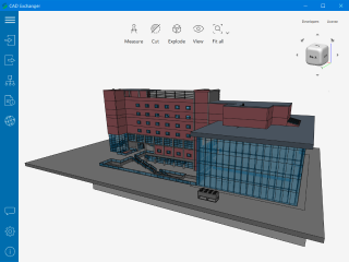
3D formats overview: IFC
In the eighth part of the series, we touch upon the neutral data exchange standard in Building Information Modeling
Read more
Integration with UNIGINE engine
This article explores the integration possibilities with the UNIGINE engine, a powerhouse in the realm of virtual simulation and game development. Learn how it can be used in applications built with the UNIGINE engine to import CAD and 3D models.
Read more