How to convert Siemens NX
to IGES?
Applications for end-users. SDK's and tools for software developers. Custom development services for businesses.
Trusted by industry leaders


Available in CAD Exchanger Products
 CAD Exchanger Lab
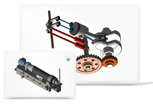
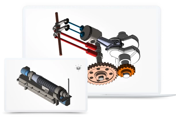
Desktop app to view, explore and convert 3D CAD data across 30+ file formats
Learn more

Siemens NX
Siemens NX is a proprietary format developed by Siemens Digital Industries Software and is optimized for seamless interoperability and efficient data exchange within the NX ecosystem. This format enables users to preserve the integrity and accuracy of their designs while facilitating collaboration and facilitating various engineering processes throughout the product lifecycle.
Support of Siemens NX files in CAD Exchanger
CAD Exchanger can import .prt files from v5 to 2212. Such support includes:
- B-Rep representations;
- polygonal representations (including multi-LODs);
- assembly structure (via external files);
- names;
- graphical PMI;
- colors.
Follow this link to check out all the CAD Exchanger products.
Pros of the format
Synchronous Technology
It is a capability integrated into the Siemens NX format that provides significant advantages for engineers and designers, including flexible editing, faster design iterations, easy collaboration, and enhanced design reuse.
Synchronous Technology allows for direct editing of geometry without being constrained by the traditional parametric modeling approach. Designers can easily modify and manipulate geometry without the need to track and update a complex history tree. Moreover, changes can be made directly on the model, providing instant feedback and allowing for quicker design optimization.
Integrated Product Lifecycle Management
One of the key advantages of the Siemens NX format is its seamless integration with Teamcenter PLM solutions. This integration allows for comprehensive product data management, including design, simulation, manufacturing, and collaboration, all within a unified environment. The tight integration of PLM capabilities ensures data consistency, reduces errors, and improves collaboration throughout the entire product lifecycle.
Cons of the format
Proprietary nature
Because the NX file format is specific to Siemens NX, developers may encounter challenges when trying to exchange data or collaborate with users or systems that utilize different file formats. This can require additional conversion or translation steps, which may introduce complexity and potential data loss or inconsistencies.
Furthermore, working with a proprietary file format restricts developers from leveraging open-source or third-party libraries and tools that are not designed to work directly with the NX format. This limits the flexibility and extensibility of developers' applications and may require more effort to implement certain functionalities.
Cost
The Siemens NX format refers to high-end CAD software, and it comes with a corresponding price tag. Compared to some other CAD tools, the licensing and maintenance costs for NX can be relatively higher. This may make it less accessible for individual users or small businesses with limited budgets. However, it's worth noting that the comprehensive features and robust capabilities of NX often justify the investment for larger organizations or industries where its unique strengths are crucial.
FAQ
What industries is the Siemens NX format commonly used in?
The Siemens NX format is widely used in industries such as automotive, aerospace, machinery, and many more. It caters to the needs of professionals involved in product design, manufacturing, and simulation.
Can the Siemens NX format be used for 2D drafting?
Yes, the Siemens NX format supports both 2D and 3D drafting and modeling. It offers a comprehensive set of tools for creating and editing 2D drawings, as well as designing complex 3D models.
Does CAD Exchanger have any limitations related to the Siemens NX format?
Yes. Siemens NX assemblies are represented with external files and it's possible for an assembly to contain components saved by different versions of NX. In case some of the components are saved by an unsupported version of NX, CAD Exchanger will not be able to load them and they will be omitted from the imported product structure.
How to open a .prt file?
To open this file, you will need a compatible software application, for example, CAD Exchanger Lab. Launch the software and navigate to the 'New file' option. Browse your computer's directories and locate the .prt file you want to open. Then select it and click "Open". Once the import process is complete, the .prt file should be loaded into the software, allowing you to view and interact with the 3D model and associated data.
History of Siemens NX format
The NX format has an interesting history that traces back to the early 1990s. It was initially developed by Unigraphics Solutions, a company founded in 1969 and later acquired by Siemens AG in 2007. Unigraphics, which later became known as Siemens Digital Industries, introduced the first version of the NX software suite in 1996.
Over the years, NX has evolved into a comprehensive and powerful CAD and CAM solution. With each new release, NX has consistently pushed the boundaries of innovation and set new industry standards. It has become a perfect choice for professionals in various industries, including automotive, aerospace, and industrial machinery.
The NX format itself has been constantly refined and enhanced to support advanced modeling techniques, simulation capabilities, and data management. It offers a range of features, such as parametric modeling, assembly design, digital simulation, and more, allowing engineers and designers to create and optimize complex products with efficiency and precision.
Today, the Siemens NX format is recognized as a leading CAD format, known for its robustness, flexibility, and compatibility with other industry-standard formats. It continues to evolve and adapt to the ever-changing needs of the engineering and design community, empowering users’ capabilities.
IGES
The IGES format was developed to provide a universal standard for exchanging 3D data between different CAD software applications. IGES files, represented in ASCII text, contain information about the geometry, structure, and attributes of 3D objects.
The IGES format enables users to share complex CAD models while preserving the integrity of the data. It supports the representation of both 2D and 3D geometries, allowing for the exchange of points, curves, surfaces, and solids.
Support of IGES in CAD Exchanger
CAD Exchanger can import IGES format files up to version 5.3, export IGES format files version 5.3. Such support includes:
- B-Rep representations;
- assembly structure;
- names;
- user-defined properties;
- colors;
- layers.
Follow this link to check out all the CAD Exchanger products.
Pros of the format
Broad Compatibility
IGES has been a long-standing industry standard for data exchange since its development in the late 1970s. Many CAD systems, both old and new, have built-in support for importing and exporting IGES files. This enables easy collaboration and data sharing between different software platforms, regardless of the specific CAD system being used.
Good capabilities for B-Rep representation
For a format that is over 35 years old, IGES provides good capabilities for representing B-Rep and even representing rigid bodies, including information on connectivity. Combined with the advantages indicated above, it makes the IGES format relevant and actively used to this day.
Cons of the format
Limited representation of B-Rep geometry
The IGES format has some limitations when it comes to fully representing B-Rep geometry. While it can effectively preserve basic geometric information like points, curves, and surfaces, there are difficulties with edge connectivity information. Most CAD writers use the older and limited capabilities of representing B-Rep through bounded and trimmed surface entities. These entities can not contain comprehensive information about the surface topology of bodies. As a result, models written in this form often have inconsistent edge orientations.
No PMI
The IGES format does not have a standardized way to represent or store PMI data. As a result, when exporting a CAD model with PMI to an IGES file, this valuable information is typically lost or not accurately transferred. This limitation can have significant implications for downstream processes, as manufacturers may rely on PMI data for carrying out manufacturing operations, quality control, and documentation.
To overcome the weakness, newer formats, such as STEP, have been developed to support the inclusion and preservation of PMI data. These formats provide dedicated mechanisms to store and communicate PMI information, allowing for a more comprehensive exchange of design intent and manufacturing specifications.
FAQ
Is IGES format specification publicly available?
Yes, it is. The IGES file format specification defines the structure and syntax of IGES files, ensuring consistency and compatibility.
Header section contains general information about the file, such as software details and creation date. Start section defines the units of measurement, coordinate system, and other global parameters. Global section describes the overall structure of the file, including directories, lists, and relationships between entities. Directory section serves as an index for entities, assigning unique numeric identifiers and specifying their location within the file. Parameter data section contains the geometric and topological information of entities. Terminate section marks the end of the file.
What are the IGES file extensions?
The file extensions used for the IGES file format are ".igs" and ".iges". Both extensions are widely recognized and can be used interchangeably to indicate files that conform to the IGES format.
How to open IGES file?
To open an IGES file, you will need a compatible software application such as CAD Exchanger Lab. Start by launching the software and navigate to the 'New file' option. Next, find the IGES file (.igs or .iges) you want to open. Once you've located the file, simply select it and click "Open". The software will then initiate the import process, and once it's complete, the 3D model and its associated data will be loaded into the software. From there, you can easily view and interact with the 3D model.
History of IGES format
The history of the IGES format dates back to the late 1970s when it was developed to address the need for a universal standard for exchanging 3D CAD data. At the time, there was a lack of interoperability between different CAD systems, making it difficult to share and collaborate on designs.
To overcome this challenge, the National Bureau of Standards (now known as the National Institute of Standards and Technology) initiated the development of IGES in collaboration with industry leaders. The goal was to create a format that would allow for the seamless exchange of geometric and topological data between different CAD systems.
In 1980, the first version of the IGES format, known as IGES 1.0, was published. It provided a standardized structure and syntax for representing 3D CAD data, allowing for the transfer of geometric entities, attributes, and relationships. Over the years, subsequent versions were released, introducing enhancements and addressing the evolving needs of the industry. Today, the most widely used version is IGES 5.3, which was released in 1996 and is still in use today.
While newer formats have emerged with improved capabilities, IGES remains relevant, particularly for legacy systems and situations where basic geometric exchange is the primary requirement.
Convert Siemens NX
to IGES
Need to work with CAD files in numerous formats? No worries.
From Siemens NX to IGES, CAD Exchanger gets you covered.
What Our Delighted Customers Say
From Our Blog
Everything you need to know about CAD file formats
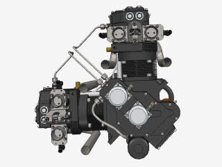
A CAD file is an output of a CAD software, containing key information about the designed object: its geometry and topology representation, 3D model hierarchy, metadata, and visual attributes depending on the format of the file.
Read more
Integration with UNIGINE engine
This article explores the integration possibilities with the UNIGINE engine, a powerhouse in the realm of virtual simulation and game development. Learn how it can be used in applications built with the UNIGINE engine to import CAD and 3D models.
Read more
Manufacturing Toolkit and Web Toolkit enhancements, Unity performance optimization, renaming and rotating SDK examples in release 3.24.0
Explore the wall thickness at a specific point on a surface, enjoy four times faster Unity objects performance, and check out renaming and rotating examples in SDK.
Read more