
How to convert VRML
to IGES?
Applications for end-users. SDK's and tools for software developers. Custom development services for businesses.
Trusted by industry leaders


Available in CAD Exchanger Products
 CAD Exchanger Lab
Desktop app to view, explore and convert 3D CAD data across 30+ file formats
Learn more

VRML
VRML (Virtual Reality Modeling Language) was originally known before 1995 as the Virtual Reality Markup Language. It is a standard file format for representing 3-dimensional (3D) interactive vector graphics, designed particularly with the World Wide Web in mind.
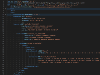
VRML is a text file format where, e.g., vertices and edges for a 3D polygon can be specified along with the surface color, UV mapped textures, shininess, transparency, and so on. URLs can be associated with graphical components so that a web browser might fetch a webpage or a new VRML file from the Internet when the user clicks on the specific graphical component. Animations, sounds, lighting, and other aspects of the virtual world can interact with the user or may be triggered by external events such as timers. A special Script Node allows the addition of program code (e.g., written in Java or ECMAScript) to a VRML file.
VRML files are commonly called "worlds" and have the *.wrl extension (for example island.wrl). VRML files are in plain text and generally compress well using gzip, useful for transferring over the internet more quickly (some gzip compressed files use the *.wrz extension). Many 3D modeling programs can save objects and scenes in VRML format.
IGES
The IGES format was developed to provide a universal standard for exchanging 3D data between different CAD software applications. IGES files, represented in ASCII text, contain information about the geometry, structure, and attributes of 3D objects.
The IGES format enables users to share complex CAD models while preserving the integrity of the data. It supports the representation of both 2D and 3D geometries, allowing for the exchange of points, curves, surfaces, and solids.
Support of IGES in CAD Exchanger
CAD Exchanger can import IGES format files up to version 5.3, export IGES format files version 5.3. Such support includes:
- B-Rep representations;
- assembly structure;
- names;
- user-defined properties;
- colors;
- layers.
Follow this link to check out all the CAD Exchanger products.
Pros of the format
Broad Compatibility
IGES has been a long-standing industry standard for data exchange since its development in the late 1970s. Many CAD systems, both old and new, have built-in support for importing and exporting IGES files. This enables easy collaboration and data sharing between different software platforms, regardless of the specific CAD system being used.
Good capabilities for B-Rep representation
For a format that is over 35 years old, IGES provides good capabilities for representing B-Rep and even representing rigid bodies, including information on connectivity. Combined with the advantages indicated above, it makes the IGES format relevant and actively used to this day.
Cons of the format
Limited representation of B-Rep geometry
The IGES format has some limitations when it comes to fully representing B-Rep geometry. While it can effectively preserve basic geometric information like points, curves, and surfaces, there are difficulties with edge connectivity information. Most CAD writers use the older and limited capabilities of representing B-Rep through bounded and trimmed surface entities. These entities can not contain comprehensive information about the surface topology of bodies. As a result, models written in this form often have inconsistent edge orientations.
No PMI
The IGES format does not have a standardized way to represent or store PMI data. As a result, when exporting a CAD model with PMI to an IGES file, this valuable information is typically lost or not accurately transferred. This limitation can have significant implications for downstream processes, as manufacturers may rely on PMI data for carrying out manufacturing operations, quality control, and documentation.
To overcome the weakness, newer formats, such as STEP, have been developed to support the inclusion and preservation of PMI data. These formats provide dedicated mechanisms to store and communicate PMI information, allowing for a more comprehensive exchange of design intent and manufacturing specifications.
FAQ
Is IGES format specification publicly available?
Yes, it is. The IGES file format specification defines the structure and syntax of IGES files, ensuring consistency and compatibility.
Header section contains general information about the file, such as software details and creation date. Start section defines the units of measurement, coordinate system, and other global parameters. Global section describes the overall structure of the file, including directories, lists, and relationships between entities. Directory section serves as an index for entities, assigning unique numeric identifiers and specifying their location within the file. Parameter data section contains the geometric and topological information of entities. Terminate section marks the end of the file.
What are the IGES file extensions?
The file extensions used for the IGES file format are ".igs" and ".iges". Both extensions are widely recognized and can be used interchangeably to indicate files that conform to the IGES format.
How to open IGES file?
To open an IGES file, you will need a compatible software application such as CAD Exchanger Lab. Start by launching the software and navigate to the 'New file' option. Next, find the IGES file (.igs or .iges) you want to open. Once you've located the file, simply select it and click "Open". The software will then initiate the import process, and once it's complete, the 3D model and its associated data will be loaded into the software. From there, you can easily view and interact with the 3D model.
History of IGES format
The history of the IGES format dates back to the late 1970s when it was developed to address the need for a universal standard for exchanging 3D CAD data. At the time, there was a lack of interoperability between different CAD systems, making it difficult to share and collaborate on designs.
To overcome this challenge, the National Bureau of Standards (now known as the National Institute of Standards and Technology) initiated the development of IGES in collaboration with industry leaders. The goal was to create a format that would allow for the seamless exchange of geometric and topological data between different CAD systems.
In 1980, the first version of the IGES format, known as IGES 1.0, was published. It provided a standardized structure and syntax for representing 3D CAD data, allowing for the transfer of geometric entities, attributes, and relationships. Over the years, subsequent versions were released, introducing enhancements and addressing the evolving needs of the industry. Today, the most widely used version is IGES 5.3, which was released in 1996 and is still in use today.
While newer formats have emerged with improved capabilities, IGES remains relevant, particularly for legacy systems and situations where basic geometric exchange is the primary requirement.
Convert VRML
to IGES
Need to work with CAD files in numerous formats? No worries.
From VRML to IGES, CAD Exchanger gets you covered.
What Our Delighted Customers Say
From Our Blog

Everything you need to know about CAD file formats
A CAD file is an output of a CAD software, containing key information about the designed object: its geometry and topology representation, 3D model hierarchy, metadata, and visual attributes depending on the format of the file.
Read more
3D formats overview: VRML and X3D
In the seventh part of the series, we explore two open formats aimed at putting 3D data on the web, which found use in the CAD space
Read more
Integration with UNIGINE engine
This article explores the integration possibilities with the UNIGINE engine, a powerhouse in the realm of virtual simulation and game development. Learn how it can be used in applications built with the UNIGINE engine to import CAD and 3D models.
Read more