My life for the last 20+ years has been around 3D formats (even if during certain period my job was not directly related to that). I started my professional career in 1997 working on improving the IGES and STEP converters in EADS Matra Datavision company.
So although most of the terms sound familiar to me and my team in CAD Exchanger, most of our customers and prospects are not that familiar with particular details of each format, even if sometimes they spent as much time in CAD industry as myself.
If you are curious to learn more about 3D formats and their peculiarities then you might find this blog post series useful. This series does not pretend to be exhaustive or too deep but it could serve you as focused one-stop guide. I remember of somewhat similar attempt made by one of the community members at grabcad which I had to comment on to suggest certain corrections.
So keep on reading.
What we’ll cover:
- IGES
- STEP
- ACIS
- Parasolid
- JT
- STL
- VRML and X3D
- IFC
- OBJ
In the end we will make a summary table to serve as a quick grasp of the format differences and commonalities.
Part 1. IGES
Introduction
IGES (stands for Initial Graphical Exchange Specification) originates from early 1980-es as an effort of select CAD vendors of that time to work out an interoperability specification.
Truth be told, CAD vendors have been following (up to now) the policy of walled-gardens and resisting interoperability trying to lock in users to own PLM system and thus formats. IGES was the first attempt to find some common language under pressure of large users including Navy and NASA.
For 15+ years (from 1980 to 1996) the IGES specification had been evolving from 1.0 to 5.3. There was a draft of IGES 6.0 but it got never approved and thus not adopted in the industry.
Despite the fact that IGES has been the first and the oldest neutral format, there is still huge amount of legacy data in the IGES format. Moreover many users for one reason or another tend to prefer using IGES adding new files in that obsolete format. Perhaps it can be attributed to “that’s the way we always did” mentality or “it’s the format which everyone can read” and lack of understanding of technical details.
Technical details

Let’s cover a few technical details and deficiencies.
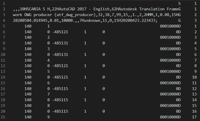
- IGES is a text-based format.
- The IGES file has five sections: Start, General, Directory, Parameters, Termination.
- Each line is 80 characters long. Some sections using tabulated representation.
- Each entity type has a type-id (type number) and optional sub-type id (form number). For instance a line is 110 Form 0 and B-Spline surface is 128.
Although, the IGES spec tries to cover a very broad scope of entities (up to meshes of 2nd order and attachment of Finite-Element solver results), the commonly supported scope among CAD systems is quite narrow.
IGES format disadvantages and weaknesses
The greatest weakness of the IGES format is its way to describe Boundary Representation (refer to the crash course to recall the concept). Unlike other B-Rep-based formats which followed that format, IGES tries to describe a body primarily via a set of disconnected surfaces instead of strict detailed topological graphs.

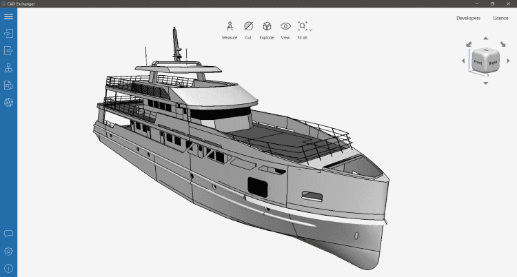
The above 3D body, although looking nice is described via a plain set of (mutually disconnected) Trimmed Surfaces (type 142). The Trimmed Surface resembles a B-Rep face but only holds a contour (or several, in the case of holes) trimming its underlying surface. Unlike a true B-Rep face, TS’s child curves do not hold references to ‘partner’ curves trimming adjacent Trimmed Surfaces. Neither do they contain information of common vertices between them.
With that lack of important details, a B-Rep model imported from IGES is most often a sheet body as a collection of topologically disconnected faces. This leads to necessity to either stitch (or sew) the faces to form a connected (and ideally closed) shell or deal with such collection in downstream applications. (For instance, necessity to compute volumes for manufacturing cost estimates app makes IGES poorly applicable to that).
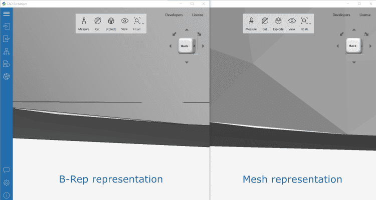
As long as the faces are disconnected the generated mesh (by triangulating each face independently) is generally not water-tight. This is because the edges are polygonized independently and the mesh nodes along curves are not coincident. This leads to leads to visually apparent cracks along the face boundaries and non-closed STL (and other) meshes, making such model unusable for 3D printing.

Later versions of IGES (starting with 5.1) did address that issue by introducing a set of entities specifically aimed to describe B-Rep solids (or open connected B-Rep shells). These entities include MSBO (Manifold Solid B-Rep Object), type 186 and others (Shell, type 514; Face, type 510; etc). For that very reason, to maximize efficiency of IGES-based data conversion, CAD Exchanger favors MSBO-based description when writing IGES files.
However, many outdated CAD applications may have challenges to read such IGES files and the user has to fall back to writing Trimmed Surfaces. Likewise, many CAD applications tend to write IGES files using the above Trimmed Surfaces by default.
(IGES offers a slightly more efficient type 143 Bounded Surfaces than type 144 Trimmed Surfaces. Type 143 provides more explicit mapping between 3D and 2D edge curve representations, similar to approach used in most modeling kernels. CAD Exchanger uses that type when writing IGES files when the user favors that approach vs MSBO which is the default).
Other deficiencies (although less severe) include:
- Single precision per entire file. Instead of local tolerances/precisions IGES uses a single precision value per file which proves it essentially useless when dealing with large multi-part assemblies, as sizes and gaps can significantly vary between different parts.
- Large file size. Due to multi-section and tabulated format IGES file wastes significant space on repeatingentity type id’s between lines and sections, and inserting blank spaces between columns.
- File size limitations. The IGES format reserves 7 characters for a rank number inside a section thereby limiting a number of lines to ten million entries. This may have seemed huge 35+ years ago, but it is no longer mind blowing today. Given that complex NURBS surfaces may take multiple lines per entity this limitation may reduce the model to hundreds of thousands entities which is not something exceptional. We have seen files which were just truncated (and thus invalid) due to line counter overflow.
- No PMI. The IGES format can transmit certain PMI-related entities (such as dimensions) but is not able to transmit traditional graphical or semantic PMI to the extent that more recent formats can. No materials and textures. Visual style capabilities are limited to colors and thus a 3D model cannot be transmitted more data-rich information.
At the same time IGES is quite capable to transmit assembly structure, colors and names.
Overall, IGES should not be recommended as a way to exchange B-Rep data and should only be used as a last resort. The closest alternative for general B-Reps would be STEP followed by the formats of the geometric modeling kernels (ACIS, Parasolid, Rhino/OpenNURBS, etc). We will review all these and other formats over time to see why they provide a better option than IGES.
Example files:
Further reading
CAD Exchanger SDK / IGES converter
Everything you need to know about CAD file formats
Next formats overview: