Other formats overview:
Introduction
JT was originally developed as a part of DirectModel toolkit by Engineering Animation and HP. The former was eventually acquired by Siemens and now JT is the standard exchange format across the whole Siemens PLM ecosystem. The name of the format stands for Jupiter Tessellation (DirectModel was originally named Jupiter), so naturally, mesh data is a cornerstone of this format both from the point of view of its implementation and its usage in the real world. In the early 2010s the format was standardized by ISO.
Technical details
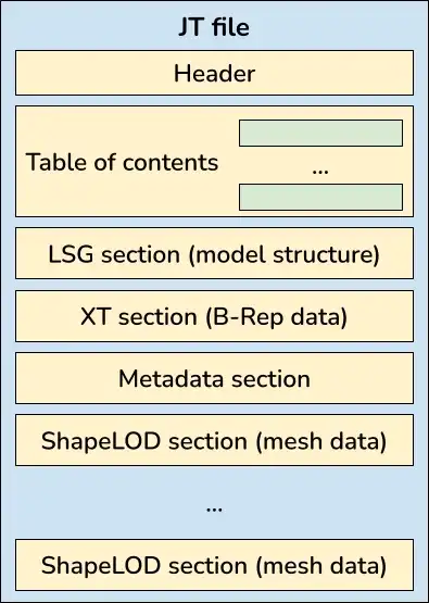
JT is a binary format and its organization is quite customary as far as the binary formats go. The data in the file is organized in sections, according to its purpose. There is a section for part-assembly hierarchy, sections for various types of geometry, for metadata and PMI. The file begins with a header with basic information about the file (JT version, writing system, etc.), followed by a table of contents listing all the sections with their locations in the file and sizes (see Fig.1).

There have been quite a few JT versions, but the latest and most common now are JT 9.x and 10.x, so we'll mostly talk about them. Even before the ISO standardization, the specifications for these versions were publicly available (together with version 8.x), unlike specifications for version 7 and earlier, when the format was effectively proprietary.
Strengths and weaknesses
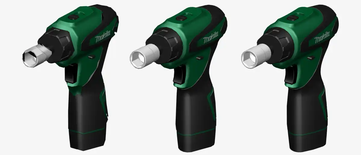
JT supports lots of types of data: part-assembly hierarchy, mesh and B-Rep geometry, metadata (layers, PMI and properties) and visual attributes (colors, materials and textures). In this regard, among neutral formats, JT is second probably only to STEP. Still, in some ways, JT is superior, in particular its storage of meshes. Once again, as the name suggests, meshes are a big focal point of the format and lots of things in it are built around them. The part-assembly hierarchy actually extends past the part level and provides a mechanism to store multiple meshes for a part, representing different levels of detail (LODs in short; see Fig. 2).

One of the key features of JT is the extensive usage of compression and economical data representations. Together with the binary nature of the format, this means that the JT files are on average smaller than STEP files with comparable geometry. Mesh data is represented especially economically by exploiting the connectedness of mesh patches with topological compression algorithms. Another aspect that contributes to this perception of JT being economical is the fact that it actively encourages late-loading of data. The idea here is that the reading software can first load the bare minimum amount of data from the file to set up its data model, and later load additional portions of data when they become necessary. The existence of LODs fits really well into this picture - for example, an application can only load the coarsest LOD to display the whole model and then load finer ones as the model is manipulated on screen.
Like STEP, JT is capable of representing complex assemblies with a hierarchy of files, each corresponding to a part or sub-assembly (see Fig. 3). Unlike STEP, JT assemblies are represented in this "shattered" manner way more often, perhaps due to the specifics of the automotive industry, where JT is used extensively. The shattered models naturally play into the concept of late-loading, allowing one to delay the import of entire parts and subassemblies.

Although mesh data is the main staple of JT, it's nevertheless quite capable at B-Rep as well. There is a variety of representations that B-Rep data can be stored in, including some lightweight schemes, but the main ones are native JT B-Rep, Parasolid and STEP. Of these three by far, the most prominent is Parasolid. Being a kernel format with a long history and widespread usage, it's a great choice for representation of any B-Rep one can think of. Still, everything said about Parasolid's complexity in our last blog post applies and poor support of Parasolid may render even an otherwise good JT implementation mediocre.
Ever since the ISO standardization in 2012, the JT is effectively an open format. Still, its long proprietary history shows: the real-world files (especially those produced by the official Siemens tools descending from the DirectModel toolkit - basically, the reference implementation) often disobey the specification. With JT being as complex as it is, this serves as a real detriment to the independent implementers. As a result, the quality of JT support can vary a lot throughout the industry.
In summary, it makes sense to use JT when one's considering a data pipeline involving any of the Siemens products, be it Teamcenter, NX, Solid Edge, etc. Within that ecosystem, the format's rich nature allows its usage for archiving and PDM purposes. Another situation where JT can be considered is when one needs to minimize the size of data, without compromising the scope or developing a custom persistence mechanism. Outside of these 2 areas outputting JT is harder to recommend due to an uneven level of support by various vendors. A truly open format like STEP should serve anyone that little bit better in general.
Example model:
Further reading