Other formats overview:
Introduction
STL (stands for stereolithography) was created in the late 1980s by the 3D printing equipment manufacturer 3D Systems. In the years since the format has become almost universal due to its simplicity while still maintaining its foothold in the 3D printing space. It can now also be encountered in CAM systems targeting classic subtractive manufacturing processes, in the data workflows resulting from 3D scanning and in general data exchange workflows. Pick any software dealing with 3D data (CAx, 3D graphics, etc.) and it will likely be capable of reading and/or writing STL data.
Technical details
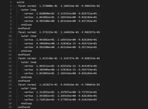
STL files have a trivial structure - a flat list of triangles (see. Fig. 1). The keywords and presence of hierarchical structure hints at the possibility of defining general polyhedral objects with voids and N-sided polygonal faces, but in practice, the STL files always contain triangular meshes. The same goes for support of multiple parts or bodies - technically one can store them in a single file, defining a few solid/endsolid groups. However, the support for such files varies across the software: some will import only the first group, others will merge the triangles from all the groups together, discarding the distinction present in the file.
Aside from the text (ASCII) variant shown in Fig. 1, there's also a binary STL format, which has exactly the same structure, but instead of keywords, the groups are defined by a fixed layout for each triangle.

Strengths and weaknesses
The best things about STL are its ubiquity and simplicity. Whatever software you're working with, you'll likely be able to connect with it using STL and the quality of the conversion (i.e. presence and general geometric features of your parts) will be decent enough.
STL is a mesh-only format, but that's only half the story. What really sets the STL apart (and not in a good way) is that the vertices for each triangle are specified separately, which means that the format doesn't hold information about vertices being shared by adjacent triangles. This setup is sometimes dubbed "the soup of triangles". So, connectivity between adjacent triangles can only be determined by comparing the vertices directly. This carries a performance penalty and a risk of inaccuracy when reading an STL file back.
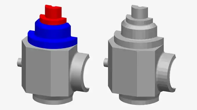
STL can carry triangle normals, but this information is often superfluous since the normal can be inferred from the vertices and the order in which they're listed. It cannot store vertex normals though, which are used to produce smooth-appearing surfaces in shading algorithms, so STL models always appear faceted (see Fig. 2).

There is no support for part-assembly hierarchy in STL, and as was pointed out previously even the support of flat part lists is quite lacking. Colors are in a similar situation - they're not supported at the level of specification, but some software is using various reserved spots in the file layout to store color information (more specifically the header line in both ASCII and binary files, and a reserved field in the triangle structure in the binary version). The portability of such tricks is clearly not the greatest. STL also doesn't specify the units used in the file, so both readers and writers usually have settings to control how the numerical values are to be interpreted - as millimeters, inches, or something else.
A special mention is warranted for a common use case - STL to B-Rep format conversion (most often STL to STEP). The need to perform such conversion arises when one has to do CAD modeling with 3D scanned data, or when receiving 3D data from unscrupulous vendors. We've covered this scenario from a conceptual point of view before, but the bottom line is that this process is basically guesswork, because of how little data there is in STL (especially compared to a B-Rep model). Although there's been some progress in this task, we're still not at the point of universal usability. Hybrid modeling techniques making their way into CAD software promise to eliminate the need for this conversion at least for some scenarios.
All these considerations paint a rather bleak picture. A portable STL file can contain only a flat list of triangles of the model, without connectivity information. Anyone considering STL in their data exchange scenario should be wary of these limitations and make sure that they are actually acceptable. If you're designing a data pipeline, make sure that no downstream stage requires rich 3D data after it's been converted to STL. If you're not sure that your scenario can manage with this little information about your 3D model, we suggest you err on the side of caution and use more feature-rich formats (e.g. OBJ, X3D, VRML, FBX; basically any other format that CAD Exchanger can export).
Example model:
Further reading