Other formats overview:
Introduction
STEP stands for Standard for Exchange of Product model data. It originated from a Product Data Exchange Specification (PDES) which was developed in the mid-1980s by the same group that created IGES. Initial aim of STEP was to supersede a few older exchange formats, such as IGES and VDA-FS and to provide a unified implementation-independent data model for products from all kinds of industries. This grand aim necessitated the specification to be split into multiple pieces, defining different aspects of product representation (structure representation, geometry representation, persistence mechanism, etc.). STEP became an ISO 10303 standard in 1994.
Since the initial standardization STEP has evolved to cover more industry-specific use cases and evolving product design practices. As of now, it is de facto the standard exchange format and every sufficiently popular and recent CAD application is capable of reading and writing STEP models.
Technical details

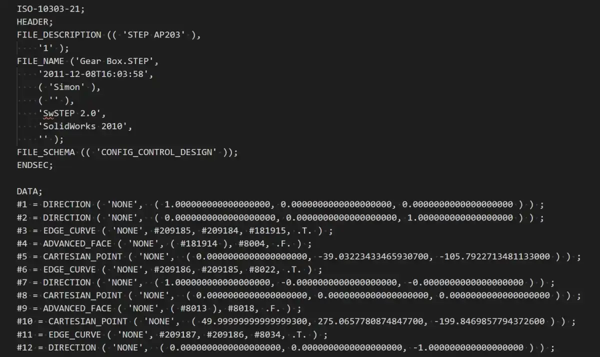
STEP models are most often represented as text files following EXPRESS schema, such as the one shown above. As every other aspect of STEP, this text representation is a portion of the standard (specifically, Part 21). There are also portions that define other representations of STEP data, though they are not used nearly as commonly. In EXPRESS form, the STEP file has 2 sections: HEADER and DATA. The DATA section contains a list of entities, each of which has an integer index, type name and a list of parameters.
The set of available entities is extremely wide, containing generic types (such as geometry and topology, product structure entities) and application-specific types. The latter are split into so-called Application Protocols (AP). They cover a variety of product-related processes (design, manufacturing, product lifecycle support) and a range of design industries (mechanical - AP203, 214, 242, electronic - AP210, construction - AP225, shipbuilding - AP218, etc.). The majority of real-world STEP files are written using mechanical CAD application protocols.
Such wide applicability comes at a cost - the structure of the format is very flexible, providing for many formally valid ways to represent the same data. This presents a challenge for implementation of reading and writing of STEP - even formally correct implementation may be incompatible with other software defeating the goal of seamless data exchange. MBx Interoperability Forum is an organization aiming to improve this situation. It releases Recommended Practices documents specifying how to utilize the STEP capabilities to represent specific data configurations (in product structure, geometry, properties, visual attributes and PMI). Applications that implement STEP in accordance with Recommended Practices have a much higher chance of being able to extract all the data from each other's STEP files.
Strengths and weaknesses
Understandably, the wide reach of STEP means that all the commonly used types of CAD data can be represented in this format. STEP models can contain B-Rep data in various forms - solid, sheet and wireframe bodies with full topological information, ensuring the passing of connectivity information. Meshes are also supported (in the form of tessellated_shape_representation entity in AP242 or faceted_shape_representation entity in AP203 and AP214). Part-assembly hierarchy can be represented within a single STEP file, or with components split off into separate files. STEP can carry all the usual types of meta-data - names of structure elements and bodies, colors, layers and user-defined properties.
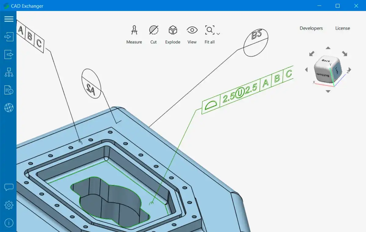
A separate mention is warranted for STEP's support of PMI, which is arguably the best among the exchange formats. AP214 and 242 provide ability to express graphical PMI (displayable entities representing PMI annotations - polylines and meshes), semantic PMI (formal machine-readable annotations - dimensions, tolerances, surface finishes, etc.) and associations between PMI annotations and B-Rep geometry (see Fig. 2).

Like I said earlier, STEP is effectively a standard exchange format, because it's supported by a wide array of applications - big brand multi-purpose CAD packages, industry-specific CAD systems, CAM software and even non-engineering 3D modeling applications. To be fair, the extent to which all this software supports STEP varies a lot. For example, a popular CAD system may be capable of writing PMI to STEP, or can save some of its own data in user-defined properties. If this file is then fed into some niche CAM software, it likely won't read this information. Still, geometry and part-assembly structure are supported pretty much across the board and for exchange of this essential data STEP is truly the most common denominator across CAD software.
However, all this interoperability prowess comes with a few downsides. Firstly, STEP is quite verbose - the long entity names and large entity graphs are there in order for the format to be as generic and applicable to many scenarios as possible, but at the same time they cause file sizes to be greater than average. Secondly, the majority of STEP models are written as text files, which can cause round-off errors in numerical values.
To sum it up, STEP is a natural choice for data exchange scenarios because of its good support for essential types of CAD data and compatibility with a wide range of software packages. It should be the preferred format for data exchange unless a more specific and suitable format exists for a particular workflow (e.g. kernel format for import into a CAD system based on that kernel - like Parasolid for import into SolidWorks).
Example file:
Further reading: