Previous parts:
What is an exploded view?

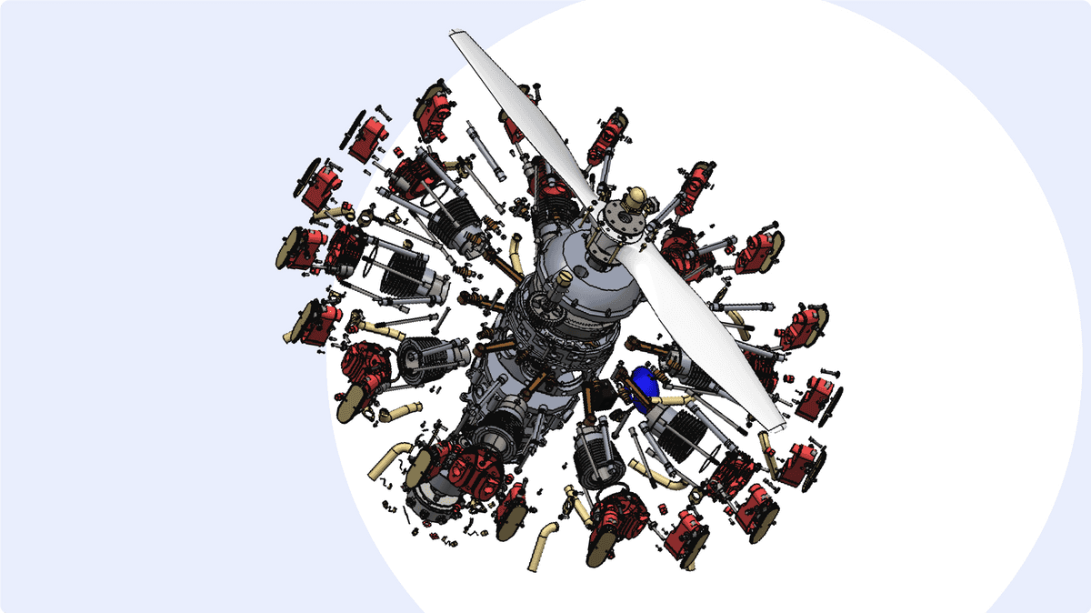
An exploded view is a technical drawing, picture, or diagram that depicts an object with its various components slightly separated. In this view, all the individual parts are arranged in the space, allowing us to observe how they work together, which would otherwise be hidden.
It is commonly utilized to represent the intricate composition of complex 3D objects, including mechanical assemblies, electronic devices, and architectural environments. By separating the parts from each other, this tool effectively unveils the specific components of interest within the object's internal structure. By disassembling the model, studying the relationships and interactions between its components, and then reassembling it, a user can gain a comprehensive understanding of how it works.
The term 'exploded view' derives from the idea that it creates the illusion that the machine's parts have been forcefully ejected outward by a controlled explosion. Exploded views are valuable because they enable a detailed examination of the object, with no parts obscured by others.
What are the benefits of using the exploded view?

1. Clear communication
Exploded views provide a clear and intuitive way to communicate complex assembly processes. They help viewers understand the spatial relationships between components, how they fit together, and the sequence of assembly or disassembly steps. It helps facilitate the identification of potential clashes or interferences between components, enabling designers and engineers to preemptively address design flaws before they manifest in the physical manufacturing phase.
2. Simplified visualization
By breaking down the assembly into individual components or subassemblies, the exploded view simplifies the visualization of complex structures. This deconstruction not only reduces the overwhelming nature of intricate designs but also provides a systematic approach to apprehending the interplay between various elements. This makes it easier to identify design errors, interferences, or clearance issues that might not be immediately obvious in a fully assembled view. Detecting and resolving these issues early in the design process can prevent costly manufacturing or assembly problems later on.
3. Enhancing design clarity
Exploded view aids users in understanding the quantity of components required and the materials used for these components. By revealing the quantity of components required, the exploded view offers a tangible sense of the assembly's complexity, which is instrumental for accurate planning in the production phase. Moreover, the explicit presentation of materials used for each component bridges the gap between design and manufacturing, ensuring that the right materials are sourced and utilized, thereby fostering both efficiency and quality in the final product.
How to use the exploded view in CAD?

Exploded views are particularly convenient in the following scenarios:
- Assembly instructions: Exploded views are often used in technical documentation, assembly manuals, or user guides. These views provide step-by-step instructions on how to assemble or disassemble a product, making it easier for technicians, assemblers, or end-users to follow the correct procedures.
- Maintenance and repair guides: For complex machinery or equipment, exploded views aid technicians in identifying parts for maintenance or replacement.
- Prototyping and rapid iteration: In the prototyping phase, exploded views enable designers to visualize their ideas quickly and experiment with different configurations. This enhances the rapid iteration process, as designers can assess how changes affect the assembly's overall structure and function before committing to physical prototypes.
How to create the exploded view in CAD Exchanger
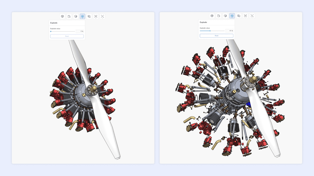
Let’s get a closer look at how to create an exploded view in CAD Exchanger Lab. You can change the level of explosion by moving the slider or by entering a specific numeric value at the toolbar above.
For developers, there is another capability in Visualization toolkit that allows to set an exploded view via the code below:
auto aViewPort = ...
aViewPort->Exploder().SetValue (0.5);
The mentioned value is an explosion value where 0.0 means unexploded view and 1.0 means fully exploded one, so you can interact with the value to examine 3D models.
You can have a closer look at the functionality of Visualization toolkit in the Exploder example.
Combining exploded view with other CAD Exchanger’s tools
With enabling/disabling individual assembly parts displayed
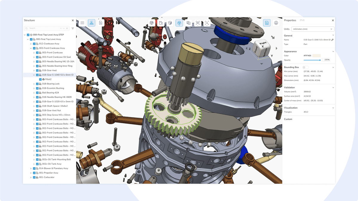
Combining the ability to enable/disable individual assembly parts in an exploded view within CAD programs offers a dynamic and versatile way to interact with complex assemblies. When the explosion is applied you can interact with parts and assemblies as usual, select one, and examine properties or change visibility.
This helps focus on specific components of interest. Users can selectively enable parts to observe their movement, interaction, and impact within the context of the entire assembly, enhancing design validation and error detection. This is particularly helpful when examining intricate assemblies with numerous parts, as users can isolate and study one section at a time for more detailed analysis.
Managing the representation in the exploded view
Zoom a model in and out to examine it more carefully and find the most fitting perspective for your analysis. Moreover, utilizing three-axis rotation (X, Y, and Z), you can view the model from multiple vantage points to identify the ideal angle that best represents it or a certain assembly.
Another feature, focus on, lets evaluate the entirety of the 3D model or concentrate on a singular component. With this feature, it is possible to both focus on the whole model and select some part of the assembly to delve deeply into the details of a chosen area.
CAD Exchanger’s functionality also allows for transitioning from one exploded part to another, facilitating a systematic examination of each part in isolation.
NB: All these features don’t impose restrictions on the use of the other capabilities.
Export an exploded view to an image

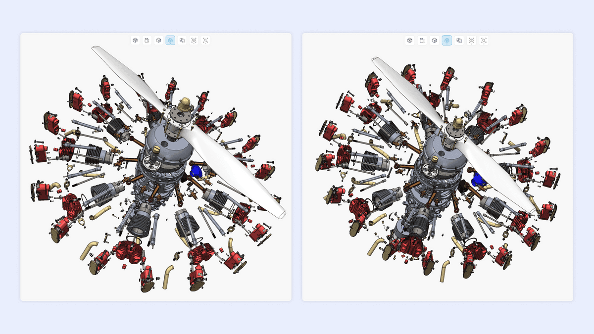
The exploded 3D model can be exported to an image and you can specify the view angle, desired position, and camera settings before generating it.
Furthermore, one of the primary choices when exporting an exploded model is the projection type selection. Isometric projection is often preferred when precise measurements and a consistent scale are crucial, while the perspective one introduces depth and realism to the image, making it suitable for creating immersive and visually engaging representations.
This level of precision ensures that the exported exploded model accurately conveys the intended message or serves its intended function.
Summary
In this blog post, we explored the concept of exploded view and its usage in CAD and reviewed the ways it could be combined with other tools. Briefly, an exploded view is used to disassemble and visually represent complex assemblies or products, which, in turn, helps simplify the designing process and prepare the model before manufacturing. It greatly enhances the efficiency and effectiveness of various processes, including assembly instructions, maintenance and repair guides, and rapid prototyping.
The utilization of the exploded view mode leads to enhancing productivity and precision but often comes at the cost of significant resource consumption. Nevertheless, this challenge can be overcome by employing specialized software such as CAD Exchanger, which simplifies and improves the process significantly.
The images and videos from this article were created using the sample assembly by Dave Goetsch via GrabCAD.