
How to convert IGES
to glTF?
Applications for end-users. SDK's and tools for software developers. Custom development services for businesses.
Trusted by industry leaders


Available in CAD Exchanger Products
 CAD Exchanger Lab
Desktop app to view, explore and convert 3D CAD data across 30+ file formats
Learn more

IGES
The IGES format was developed to provide a universal standard for exchanging 3D data between different CAD software applications. IGES files, represented in ASCII text, contain information about the geometry, structure, and attributes of 3D objects.
The IGES format enables users to share complex CAD models while preserving the integrity of the data. It supports the representation of both 2D and 3D geometries, allowing for the exchange of points, curves, surfaces, and solids.
Support of IGES in CAD Exchanger
CAD Exchanger can import IGES format files up to version 5.3, export IGES format files version 5.3. Such support includes:
- B-Rep representations;
- assembly structure;
- names;
- user-defined properties;
- colors;
- layers.
Follow this link to check out all the CAD Exchanger products.
Pros of the format
Broad Compatibility
IGES has been a long-standing industry standard for data exchange since its development in the late 1970s. Many CAD systems, both old and new, have built-in support for importing and exporting IGES files. This enables easy collaboration and data sharing between different software platforms, regardless of the specific CAD system being used.
Good capabilities for B-Rep representation
For a format that is over 35 years old, IGES provides good capabilities for representing B-Rep and even representing rigid bodies, including information on connectivity. Combined with the advantages indicated above, it makes the IGES format relevant and actively used to this day.
Cons of the format
Limited representation of B-Rep geometry
The IGES format has some limitations when it comes to fully representing B-Rep geometry. While it can effectively preserve basic geometric information like points, curves, and surfaces, there are difficulties with edge connectivity information. Most CAD writers use the older and limited capabilities of representing B-Rep through bounded and trimmed surface entities. These entities can not contain comprehensive information about the surface topology of bodies. As a result, models written in this form often have inconsistent edge orientations.
No PMI
The IGES format does not have a standardized way to represent or store PMI data. As a result, when exporting a CAD model with PMI to an IGES file, this valuable information is typically lost or not accurately transferred. This limitation can have significant implications for downstream processes, as manufacturers may rely on PMI data for carrying out manufacturing operations, quality control, and documentation.
To overcome the weakness, newer formats, such as STEP, have been developed to support the inclusion and preservation of PMI data. These formats provide dedicated mechanisms to store and communicate PMI information, allowing for a more comprehensive exchange of design intent and manufacturing specifications.
FAQ
Is IGES format specification publicly available?
Yes, it is. The IGES file format specification defines the structure and syntax of IGES files, ensuring consistency and compatibility.
Header section contains general information about the file, such as software details and creation date. Start section defines the units of measurement, coordinate system, and other global parameters. Global section describes the overall structure of the file, including directories, lists, and relationships between entities. Directory section serves as an index for entities, assigning unique numeric identifiers and specifying their location within the file. Parameter data section contains the geometric and topological information of entities. Terminate section marks the end of the file.
What are the IGES file extensions?
The file extensions used for the IGES file format are ".igs" and ".iges". Both extensions are widely recognized and can be used interchangeably to indicate files that conform to the IGES format.
How to open IGES file?
To open an IGES file, you will need a compatible software application such as CAD Exchanger Lab. Start by launching the software and navigate to the 'New file' option. Next, find the IGES file (.igs or .iges) you want to open. Once you've located the file, simply select it and click "Open". The software will then initiate the import process, and once it's complete, the 3D model and its associated data will be loaded into the software. From there, you can easily view and interact with the 3D model.
History of IGES format
The history of the IGES format dates back to the late 1970s when it was developed to address the need for a universal standard for exchanging 3D CAD data. At the time, there was a lack of interoperability between different CAD systems, making it difficult to share and collaborate on designs.
To overcome this challenge, the National Bureau of Standards (now known as the National Institute of Standards and Technology) initiated the development of IGES in collaboration with industry leaders. The goal was to create a format that would allow for the seamless exchange of geometric and topological data between different CAD systems.
In 1980, the first version of the IGES format, known as IGES 1.0, was published. It provided a standardized structure and syntax for representing 3D CAD data, allowing for the transfer of geometric entities, attributes, and relationships. Over the years, subsequent versions were released, introducing enhancements and addressing the evolving needs of the industry. Today, the most widely used version is IGES 5.3, which was released in 1996 and is still in use today.
While newer formats have emerged with improved capabilities, IGES remains relevant, particularly for legacy systems and situations where basic geometric exchange is the primary requirement.
glTF
glTF is an open standard file format for 3D scenes and models. It's designed to be compact and efficient, making it easy to distribute and render 3D content on various platforms and devices.
glTF files contain information about the 3D scene, including geometry, materials, animations, and more. They can be used in different applications, from gaming and virtual reality to augmented reality and web-based 3D experiences.
Support of glTF in CAD Exchanger
CAD Exchanger can import and export glTF 2.0 files in binary (.glb) and text (.gltf) format. Such support includes:
- polygonal representations;
- assembly structure;
- names;
- colors, materials, textures;
- user-defined properties;
- PMI as polylines (export only).
Follow this link to check out all the CAD Exchanger products.
Pros of the format
Efficiency
All the basic data (vertices, triangles, normals, UV coordinates, etc.) are contained in binary form and can also be further compressed. Besides, the file structure is carefully organized to ensure that there is no extra or redundant data. Thus, the file contains only the necessary information to define the 3D scene, without any unnecessary clutter. By eliminating redundant data, glTF files become more lightweight and easier to process.
Cross-Platform Compatibility
It is an open standard supported by a wide range of platforms and applications. This allows for seamless integration between different software, making it easier to share and view 3D models across various devices. Whether it's a web browser, a virtual reality headset, or a mobile device, glTF ensures that your 3D content can be experienced on different platforms without any compatibility issues.
Cons of the format
Lack of Backward Compatibility
glTF has seen rapid development and improvements over the years, which means that older versions may not be fully compatible with newer software or engines. This can be a challenge if you are working with older files and need to use them in a newer environment.
Limited support of advanced features
For more advanced usage scenarios it may be important that this format has limitations in the areas of animation and lighting. In particular, there is inadequate support for keyframe animation with cubic interpolation, animation of rotation angles, and tension-continuity-bias animation curves. glTF also doesn't support lights and multiple attenuation models.
FAQ
What are the glTF file extensions?
glTF files typically have the extension ".gltf" or ".glb". The ".gltf" extension is used for the textual representation of the glTF file format. It is a human-readable JSON file that contains all the necessary information to define the 3D scene structure, including geometry, materials, animations, and more.
The ".glb" extension represents the binary version of the glTF format. It is a binary file that contains all the data, including the scene hierarchy, geometry, textures, and more, in a compact and optimized manner.
How to open an .glTF file?
To open this file, you will need a compatible software application, for example, CAD Exchanger Lab. Launch the software and navigate to the 'New file' option. Browse your computer's directories and locate the .gltf file you want to open. Then select it and click "Open". Once the import process is complete, the .obj file should be loaded into the software, allowing you to view and interact with the 3D model and associated data.
History of glTF format
This format was initially introduced by Khronos Group in 2015. The initiative aimed to create a common, royalty-free specification for efficient transmission of 3D content, with a focus on real-time applications and web delivery.
The first version, glTF 1.0, was released in 2015, providing a foundation for 3D asset transmission. Building upon the success of glTF 1.0, the Khronos Group released glTF 2.0 in 2017, which brought significant improvements and expanded capabilities. glTF 2.0 introduced a more efficient binary file format, enhanced support for physically-based materials, skeletal animations, and more advanced rendering features. It also introduced a clear separation between the JSON scene description and binary data, allowing for more efficient transmission and loading.
Since then, glTF has gained widespread adoption and support across the industry. Numerous software tools, engines, and platforms have embraced glTF as a standard for delivering 3D content. The format continues to evolve with regular updates and extensions, addressing new requirements and advancing the state of 3D content transmission.
Convert IGES
to glTF
Need to work with CAD files in numerous formats? No worries.
From IGES to glTF, CAD Exchanger gets you covered.
What Our Delighted Customers Say
From Our Blog

Everything you need to know about CAD file formats
A CAD file is an output of a CAD software, containing key information about the designed object: its geometry and topology representation, 3D model hierarchy, metadata, and visual attributes depending on the format of the file.
Read more
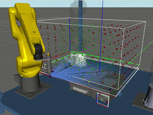
Realtime Robotics enhances responsive workcell monitoring by reading CAD files with CAD Exchanger
CAD Exchanger enables RapidSense and RapidPlan to read 3D CAD formats thanks to a unified API, fast data processing, adjustable meshing, and cancellation support.
Read more
3D Formats Overview: IGES
We will start a series of a blog posts dedicated to different 3D CAD file formats. We begin with the veteran among CAD data - IGES.
Read more