Other formats overview:
Introduction

OBJ, also known as Wavefront OBJ, was created in the 1980s by Wavefront Technologies. Its Advanced Visualizer, a 3D animation software package, consisted of a few narrowly focused tools each targeting a specific task - modeling, animation, particle animation, etc. OBJ was among the file formats used to represent the project data and move it between these tools. Later Wavefront Technologies went through a few mergers and acquisitions and Advanced Visualizer no longer exists. But the OBJ, being an open format, ended up widely used and supported by all kinds of 3D graphics software. Now it is effectively a standard 3D format, commonly used for data exchange both by end-users and in automated processing workflows.
Technical details
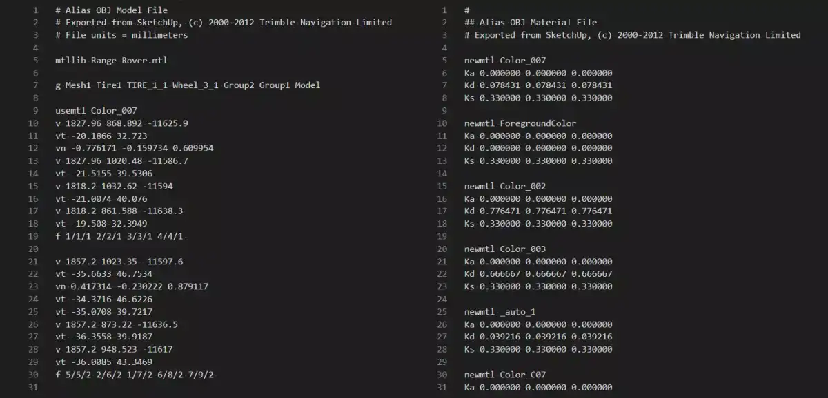
OBJ is a text format and each line hosts an item definition. Items include things like vertices, texture coordinates, normals, faces, and groups. The items in each category are numbered implicitly starting with 1, making it possible, for example, for face definitions to reference vertices, texture coordinates, and normals. To apply colors, materials, and textures to items, these have to be defined in a separate MTL file, which can be referenced from the OBJ file (notice mtllib on Fig. 2). The MTL file is structured similarly, but the items here are materials and their parameters. Both OBJ and MTL files can contain comments, they are marked with pound (#) character. These are typically used to store the identification of exporting software and also some application-specific information (see that on Fig. 2 the exporter used the comment to define the units the model was written in).

Strengths and weaknesses
Time-proven, simple and universal
OBJ is a mesh format with a solid base. It's got the indexed triangle sets for efficient storage of meshes and preservation of connectivity and line sets for the wireframe geometry. It supports vertex attributes - normals and texture coordinates. It can assign materials (similar to OpenGL's fixed-pipeline materials) and a variety of textures (diffuse, bump, reflection, etc.) to the geometry.
OBJ has a simple structure and is text based, so it's easy to tinker with. It's also easy to create an exporter from scratch and even extend the format with your own types of data in a similar fashion. The simplicity and openness of the format have allowed it to catch on and now it's hard to find software importing or exporting 3D data that doesn't understand OBJ.
Feature limitations
Being an older format, OBJ lacks many features that are now standard in other 3D formats: animation data (skeletons, morph targets), lights, LODs, advanced materials. OBJ doesn't feature any built-in compression/encoding to ensure manageable file sizes on large models that are so common today.
Importantly for CAD data exchange, OBJ lacks proper structure support with nesting and instancing. Instead, OBJ only provides a simple grouping of the geometry, so the conversion of any sufficiently complex CAD model will result in inflated file size due to the explicit copying of instanced parts (see Fig. 3). Another missing feature important for export from CAD is the support for metadata.

The wide software support also has a few caveats. OBJ capabilities range in popularity and frequency of use from strictly necessary to effectively ignored. So, the support of OBJ varies between software (and often depends on the software's own capabilities) and some data in the file might be ignored. If the OBJ model was written by software that extended the format to store some of its own special data, other software is unlikely to take advantage of this extension. Another important point is that OBJ doesn't specify used length units and up-axis orientation. Different software uses different conventions here and the importers and exporters usually present a list of options for these properties of the model. An automated data processing workflow will have to be wary of the differences in the interfacing software and apply scaling and rotation appropriately.
Summary
Because of the limited scope of data OBJ is not the first recommendation, whether you're working with CAD or 3D graphics. For CAD the biggest issue is lack of nested structure, for 3D graphics - a lack of many types of data that comes standard in other formats. In general, it's better to first consider more feature-rich mesh formats, such as FBX, glTF, or USD. OBJ remains a good fallback option though. It can prove useful when doing software MVPs to save time on the design of data workflow.
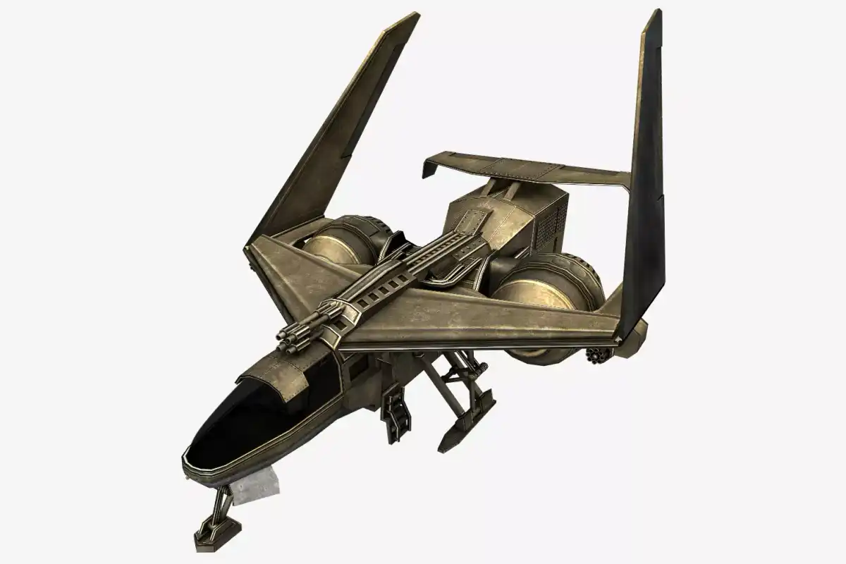
Example model:
Further reading